5 factors that impact thermal mass flowmeter accuracy, flow profile and conditioning
The velocity profile is used to determine the flow rate of a fluid flowing within a pipe. If the fully developed profile changes, a thermal mass flowmeter’s accuracy decreases. Additionally, five application factors that affect the meter’s accuracy require consideration. One of these includes the upstream straight run distance, which changes the flow profile. In many cases, flow conditioning, a process of synthetically creating a more uniform flow profile, is necessary when upstream straight run lengths are not available to achieve a sufficiently developed flow profile.
This article reviews flow profile fundamentals, the five end-user application considerations, and it explores the use of flow conditioning to improve a flowmeter’s accuracy in areas where sufficient flow profile is unattainable.
Flow profile fundamentals — Velocity profile
Fluids, such as gas, flow at varying velocities within a pipe. As gas enters a circular pipe, the particles in contact with the pipe’s surface stop, creating a boundary layer. The gas that flows in adjacent layers slows from friction and the gas velocity in the midsection increases to maintain the mass flow rate through the pipe. The velocity distribution across the pipe is the velocity profile. The flow profile becomes parabolic once the flow is "fully developed." By understanding the velocity profile, it is possible to determine velocity anywhere within the pattern.
By understanding the velocity profile, it is possible to determine velocity anywhere within the pattern.
Anytime a flow profile degrades, the meter’s accuracy drops. The main factors that affect flow profile are piping and straight run upstream of the flow sensor, with some minor impact from the downstream straight run. In a perfect world, the desired fully developed flow profile occurs with smooth and long-running straight pipe that precedes the meter’s sensor. In the real world, however, most pipelines do not have sufficient straight run, and flow disturbances arise because of fittings/couplings, expanders, reducers, valves, tees, headers, bends, filters, strainers, knockout drums, heat exchangers, regulators, valves, flanges and elbows.
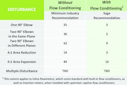
Often, the straight run preceding the meter requires increased distances to deliver the proper flow profile. For example, when introducing an elbow on the same plane of a line, it will require that the upstream straight run be 25 pipe diameters. Even longer lengths are needed for other upstream configurations. Often, sufficient straight run to secure a fully developed flow profile is unattainable. In these cases, flow conditioning is an excellent option to explore.
90-degree elbow effect on velocity profile
‘Location, location, location’
The location for a flowmeter installation is essential and often overlooked. Selecting an installation location solely based on ease of installation is often shortsighted. The end user should consider the location’s flow disturbances before choosing the position for a meter. For this reason, give thoughtful consideration to determining the most effective site. In any case, once the location is selected, identify the disturbances so the manufacturer can determine if flow conditioning is required, and if so, the flowmeter would be factory-calibrated with conditioning.
Flowmeter factory calibration
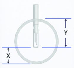
The flowmeter sensor probe must be installed in the center of the pipe.
When measuring a gas using a thermal mass flowmeter, it is important that the manufacturer understands the process conditions of the end user’s application for the meter. This way, the manufacturer can calibrate the instrument matching the circumstances of the application’s site. Without doing so, flow rate inaccuracies can result.
During the manufacturer’s flow bench calibration, a controlled amount of specified gas flows past the sensor and the signal is measured. This process is repeated many times over the operating range to determine the relationship between mass flow and the signal for the gas and sensor under calibration.
Inline body flow conditioning
The following may resolve wet gas issues when measuring with thermal mass flowmeters:
a) Angle the sensor 45 degrees in the pipe so that if condensate develops in the pipe wall, gravity moves the moisture away from the sensor.
b) When using a knockout drum, or knockout pot, the moisture drops separate from the gas. In this case, the gas flows into the vessel where a reduction in velocity and a change in direction occur. Gravity causes the moisture to fall while the gas flows up and out, removing the moisture from the gas.
c) In some cases, heat tape can be applied on the outside surface of a pipe to prevent condensation.
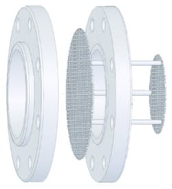
Captive flow conditioner for insertion-style meter
Flow conditioning straight run requirements
Multiple disturbances upstream of the meter have a cumulative effect on the flow profile. If achieving the correct straight pipe upstream length at the meter is not possible, flow conditioning is viable.
Flow conditioners (also referred to as flow straighteners) can deliver a uniform flow profile at the sensor location. This consistent flow profile is different from the fully developed flow profile that occurs when there is an acceptable straight run length, so it is essential to calibrate the flowmeter with the flow conditioner with an understanding of the site’s other parameters (i.e., gas type, pipe characteristics, straight upstream run length [and disturbances] and installation depth).
Flow conditioners — If insufficient straight run exists, two flow conditioner styles deliver a uniform flow profile.
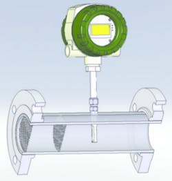
Inline flow body — For one inline flow body meter, the flow conditioning is built into the flowmeter body.
Captive flow conditioning — For insertion-style meters, a captive flow conditioner assembly that consists of two conditioning plates situated between two flanges can be effective. The end user supplies flanges for this configuration.
Table 1. This chart demonstrates the importance of flow conditioning with the recommended pipe diameters upstream.
Table 1 shows the upstream straight run length required for various pipe configurations for installations with and without flow conditioning ahead of the flowmeter location. This applies to inline body and insertion-style flowmeters (which have built-in flow conditioning).
In all cases, flow conditioning can significantly reduce the recommended upstream distance ahead of the meter.
Conclusion
When considering thermal mass flowmeters in any application, determine the location wisely and understand that the most convenient location will likely not generate the most accurate results. Provide the thermal mass flowmeter manufacturer with end-user application conditions (the pipe information, gas or gas mix, process pressure, and upstream straight run and disturbances), so it can be determined if flow conditioning is required. Then, the meter can be properly factory-calibrated to produce the most accurate meter for the application.
Reference
- Sage Prime Meter Manual (page 15).
Gary Russell is director of engineering of Sage Metering. He has a master’s degree in mechanical engineering and more than 25 years of experience in thermal mass flowmeter design and project management, including improving calibration systems, developing flow conditioning strategies, implementing gas correlations and design improvements. He may be reached at [email protected] or 866-677-7243.
