Calibration is not an absolute operation, but rather a comparison. A device’s performance is evaluated against a reference standard, which can take various forms depending on the quantity that is being measured. In flow measurement terms, a standard is a system that comprises of a measure of fluid quantity over a time period and subsidiary measurements to determine the fluid conditions, properties and influencing factors. All the measurements in the system are part of the standard, not just the measured quantity.
To have confidence in the reference standard measurement, all contributing measurements in the system must demonstrate traceability to higher level measurements and ultimately to national and international standards. This is outlined in the various standards and guidelines, such as ISO 17025.
To correctly express the performance accuracy of any standard or measurement system, the uncertainty must be evaluated and quantified. The uncertainty of the measurement is determined by analyzing and summating all the individual sources of uncertainty that pertain to the system. Uncertainty can then be expressed as the measured value alongside the absolute or relative uncertainty, where there is a given level of confidence that the true value lies within the uncertainty range.
For flow measurement applications, the confidence in the result lying within the uncertainty is normally quoted with a “coverage factor” of k=2, which is approximately 95% confidence level — meaning we are 95% confident that the true value lies within the stated uncertainty range associated with the measured value. All calibration results should have a stated uncertainty and “coverage factor” on the calibration report or certificate.
Accuracy is not the only measure of performance that is evaluated during a calibration. Another important performance indicator is the repeatability of the device — how closely the group of measurements lie. A device with good repeatability will typically have a lower measurement uncertainty associated with it. Even if there is an error or bias in the device’s measurement from standard, this can be easily corrected. If the repeatability of the device is poor, it is very difficult to improve the accuracy. Reproducibility is also important, as it is an indication of the device’s ability to reproduce the same performance when the same flow rate and conditions are repeated on a different occasion.
Flow calibration methods
There are many different methods of flowmeter calibration, and these will vary in their techniques, methods and implementation. However, they can be placed under three categories: laboratory calibration methods, master meters and verification methods.
Laboratory calibration standards can be considered as being “bucket and stopwatch” systems, whereby the bucket is a vessel that is weighed or has a known volume, and the stopwatch aspect is the time taken to fill the vessel. The quantity of fluid collected is measured and compared with the test meter reading, and since the time to fill the vessel is known, the flow rate can be calculated. The “Standing start and stop” calibrations of flowmeters are the simplest method available and can be used for both high and low accuracy calibrations. With this method, the fluid flow is started and stopped using a valve, and the timing begins as soon as the flow starts. The timing then ends when the flow is stopped.
The “flying start and finish” method is sometimes called the diverter method, where the flow through the meter is not stopped but continues uninterrupted and is physically diverted between a return path to the liquid supply tank and the collection container. A switch on the diverter mechanism starts and stops a timer and a pulse totalizer. An advantage of this method over “standing start and stop” is that the line conditions can be better controlled. Since the flow is never physically stopped, temperature control and stability are generally better.
“Bucket and stopwatch” systems are not the only option for laboratory calibrations; dynamic options are available where the flow is continuous through the device under test as well as the standard. This is normally referred to as the “master meter” method. The comparison is made between the device under test and the master meter, which is traceable to national and international standards. Master meter systems are generally less accurate than other laboratory calibration methods. However, they have an advantage of being much more compact and can easily be transferred between locations.
Outside of the laboratory setting, where calibration or verification is required in the field, the master meter method can also be used. Normally, these are other flowmeters, but for high-accuracy applications, a prover loop is used. This is incredibly useful in the field as it can allow the meter to be calibrated in-situ, provided there is a dedicated stream. A prover loop consists of a dedicated flow stream with a known volume between detectors. As the fluid flows through the prover, a timer is started at detector one and stopped at detector two, and an accurate volume flow rate is determined. Provers can use different fluids and operate at different temperatures and pressures, and if the appropriate corrections are applied, the results will be accurate. Provers offer similar measurement uncertainty to laboratory calibrations and allow for live fluids to be used.
Verification methods can be used to provide confidence in a measurement but is not technically a calibration since the check meter will normally be of comparable or poorer accuracy. It is often used where meters cannot be removed from service, but an indication of the meter’s performance must be acquired. Typically, these verification devices fall into the categories of non-invasive (or clamp-on) technology or insertion methods. These methods tend to be portable (although insertion methods require some infrastructure to be in place), can be installed when the line is operating and provide a rough indication of the flow rate (1% to 5%).
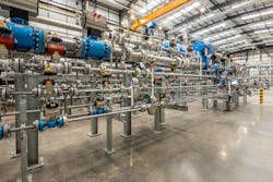
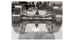
Laboratory gas calibrations tend to use a purpose-built closed-loop system, which relies on a primary standard, such as a volumetric prover or gravimetric system. This system is then used to calibrate the “working” or “secondary” standard, normally comprising of a reference flowmeter or sonic nozzle assembly. The secondary standard is then compared with the test meter to evaluate its performance.
The importance of calibration fluid and conditions
Calibration conditions are an important aspect in the flowmeter calibration process. All flowmeters are influenced to some extent by the fluid properties and flow profile presented at the device under test. As the fluid passes through the pipe, the velocity profile across the pipe is influenced by the internal diameter, roughness and Reynolds number. Reynolds number is a function of the physical properties of the fluid, the pipe geometry and flow rate of the fluid. Since Reynolds number can have a large influence on the performance of the flowmeter, it is important to ensure that the operational range of Reynolds number is covered during the calibration. For example, calibrating a flowmeter in water and using it for a hydrocarbon with a greater viscosity, will likely result in a significant measurement bias introduced through an inappropriate calibration factor.
Since flow profile can have an influence on the performance of a flowmeter, consideration must be given to the installation. Flowmeters are designed to operate in “fully developed flow,” where there is minimal distortion of the symmetrical distribution of velocity across the section of a pipe. Process equipment, pipe geometry changes, bends and valves introduce asymmetrical and possibly swirling flow. The resulting disturbances in the flow profile are referred to as installation effects and can cause errors in the measured flow through the meter. The magnitude of these effects will depend on the type of disturbance and the type of flowmeter that is being used. Coriolis flowmeters are typically considered to be immune to installation effects and are a good choice where the installation may not be ideal. Traditional metering technologies such as turbine and differential pressure meters can be highly influenced by swirling and asymmetric velocity profiles and require careful consideration when designing the installation.
In an ideal world, it would be best to calibrate the test meter in-situ, using the fluid it will measure in use. Practically speaking, this usually is not possible, and so it is important to try and replicate, as close as practically possible, the conditions that the flowmeter will be subjected to in service. This can include using the same pipework configuration and a fluid with similar properties. It is seldom possible to perfectly match the service conditions and installation, but any error due to this would be small and accounted for in the uncertainty of the device.
How often should a flowmeter be calibrated?
The interval for calibration will depend on the type of measurement being made and why. Often, industry standards or a third-party (regulator or trading partner) dictate the frequency of calibration where high accuracy measurement is required. This can include custody and fiscal transfer, where the interval is chosen to minimize the risk of an incorrect meter reading, which can result in a mismeasurement scenario.
For many other applications, however, it is the user who must define the calibration interval and type of calibration required. The frequency of calibration can be selected using three different approaches: calendar-based, risk-based and condition-based intervals. The calendar-based approach relies on a selected time period between calibrations. Risk-based intervals use previous calibration data to estimate drift in the measurement, providing a realistic and evidence-based interval. Condition-based intervals are determined using meter diagnostics to provide an indication of the meter’s health. In this case, the meter tells the user when a calibration is required.
Whatever the frequency, it is always good practice to keep calibration graphs and control charts of the meter performance as this will assist in interval selection and highlight changes in performance that may indicate degradation of meter performance.
Whatever methods are chosen, it is important to consider that the calibration applies to that meter only, operating under the conditions with which it was calibrated. If these conditions are changed in service, the calibration may not apply and it may be time to recalibrate the meter.
Calibration is an essential part of successful process operations, and without it, there would be little confidence in measured values. For flowmeters, there are many more considerations the end-user must be aware of to ensure a correct and transferable calibration is performed on their equipment. Care must be taken deciding when, where and how to complete the calibration with guidance in this article providing some key information for end users.
Harry Clark is a facility lead at TÜV SÜD National Engineering Laboratory, a world-class provider of technical consultancy, research, testing and program management services. Part of the TÜV SÜD Group, it is also a global center of excellence for flow measurement and fluid flow systems and is the U.K.’s Designated Institute for Flow Measurement.

Harry Clark | Facility Lead
Harry Clark is a facility lead at TÜV SÜD National Engineering Laboratory, a world-class provider of technical consultancy, research, testing and program management services. Part of the TÜV SÜD Group, it is also a global center of excellence for flow measurement and fluid flow systems and is the U.K.’s Designated Institute for Flow Measurement.


