Methane emission sources and monitoring to address climate change
Climate change is here and has been caused by human activities triggering the release of greenhouse gases (GHG) into the air, leading to global warming. The two most significant GHG emissions are carbon dioxide and methane. While carbon dioxide emissions are the most significant by volume, methane has a significantly higher global warming potential. It becomes a critical component in the strategy to reduce emissions and prevent global warming.
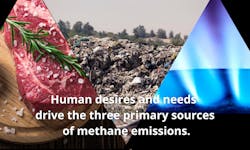
There are three primary sources of methane emissions, all caused by human desires and needs, and there are protocols to mitigate and monitor emissions of targeted sources. The thermal mass flow meter is recognized as the most appropriate device to monitor emission reductions and meet such demands.
This article focuses on mitigating methane’s impact on global warming rather than addressing the urgent global and national efforts to slow down the dangerous rise of carbon dioxide levels.
Climate change
Climate change, also called global warming, refers to the rise in average surface temperature on Earth. An overwhelming consensus from the scientific community, governments, coalitions and international organizations maintains that climate change is primarily due to human use of fossil fuels, which releases greenhouse gases into the air. The gases that trap heat within the atmosphere have deleterious effects on the planet, including record-breaking temperatures, rising sea levels, an increase in hurricane frequency and intensity, extreme flooding and severe droughts resulting in dramatic growth in wildfires.
The U.S. Environmental Protection Agency, the National Oceanic and Atmospheric Administration and the National Aeronautics and Space Agency concur that climate change is primarily due to human activity. The primary cause of climate change is burning fossil fuels, such as oil and gas, which emits greenhouse gases into the atmosphere, primarily carbon dioxide. Other contributors to climate change are agricultural activities and land use, deforestation, landfills and wastewater treatment.
Greenhouse gas emissions
Since 2010 the EPA has collected annual emissions data from industrial sources that emit significant greenhouse gases. Generally, individual facilities that emit more than 25,000 metric tons of carbon dioxide (CO2) equivalents per year are required to report. This data helps guide policymakers in their decisions related to reducing such emissions. Primary sources of carbon dioxide emissions include fossil fuel combustion, non-energy use of fuels, iron and steel production, cement production, petroleum systems, natural gas systems and petrochemical production.
In addition to carbon dioxide, which accounts for roughly 80% of the nation’s emissions, methane (CH4) is the second most significant greenhouse gas accounting for about 10%. The balance includes various sources of nitrous oxide (N2O) (primarily from agricultural activity), accounting for roughly 6%. Worldwide, carbon dioxide makes up more than 70% of the greenhouse gas emissions, and methane accounts for about 20%.
Global warming potential
The Global Warming Potential (GWP) is an index that compares the impact of different greenhouse gases. It measures how much energy the emissions of 1 ton of gas absorb over a given time, relative to 1 ton of carbon dioxide. Essentially the higher GWP means the gas contributes more to global warming. Carbon dioxide is the reference greenhouse gas; therefore, it has a global warming potential (GWP) of 1.
Methane dissipates from the atmosphere after about ten years, while carbon dioxide can hang around for hundreds of years. However, methane is more efficient at trapping radiation versus carbon dioxide. Methane’s GWP reflects the net effect of the shorter lifetime in the atmosphere and higher energy absorption. The GWP for methane is 28–36, revealing the importance of reducing methane emissions to mitigate the effects of global warming.
3 sources of methane emissions by human needs
1. Meat & meat products
The primary anthropogenic source responsible for methane emissions is humanity’s yearning for meat and meat products. Livestock farmers raise cattle, sheep, goats, and buffalos for their meat and milk. The ruminant animals’ natural digestive process generates enteric methane and accounts for up to 30% of the methane emissions globally.
2. Fossil fuel transportation
Natural gas leaks or evaporation associated with oil and natural gas and coal transportation account for the second source of methane emissions.
3. Waste management & agricultural waste
Landfills and agricultural activities, particularly from farmyard and poultry manure, also contribute to methane emissions.
Methane emission sources
Efforts to mitigate methane emissions are not complicated, create dramatic results and can be achieved relatively quickly. The United Nations recently reported that cutting methane emissions by nearly half within the next decade would prevent a 0.3°C rise in the average global temperature by the 2040s. These efforts are critical to achieving the Paris Agreement's goal of preventing a temperature rise of 1.5°C above pre-industrial levels.
Agricultural sources
Since agriculture accounts for such a large percentage of human-caused methane emissions, it is undoubtedly a key target for mitigation. Strategies include preventing the burning of fields after harvests, regularly draining rice paddies, and adjusting the type of feed for livestock, so the animals release less methane.
Promoting better animal health and improving performance through breeding can also reduce the livestock’s natural enteric fermentation. Increasing the ratio of animals dedicated to production rather than reproduction at the herd level also helps. Finally, improving grazing and grassland management can be a factor since it can enhance feed quality and productivity.
Mitigating and monitoring agricultural sources
In 2000, the California Legislature established the Climate Action Reserve’s Livestock Project Reporting Protocol to guide those installing a manure biogas control system (BCS) that captures and destroys methane in livestock operations. These operations include dairy, cattle and swine farms. The project guides the developer in calculating, monitoring, reporting and verifying greenhouse gas emissions reductions related to installing their system. The objective is to quantify the change in methane emissions and carbon dioxide emissions.
The biogas system consists of a lagoon to capture the animal waste and a large cover known as a digester. Biogas forms in the digester as the organic material breaks down, typically 65% CH4 and 35% CO2. The reduction in methane within the biogas mix is a less potent contributor to global warming. Additionally, with a good monitoring and data management system (which includes piping from the digester and an accurate gas flow meter), the biogas can be routed to a destruction device such as an engine-generator set, a boiler or a flare.
Carbon credits
The trading mechanism established in conjunction with the Livestock Protocol, known as California’s Cap-and-Trade Program, spawned numerous renewable energy projects similar to the manure management systems described above to generate carbon credits. Carbon Credits can be generated for voluntary purchase by corporations and organizations with sustainability initiatives and qualified emitters such as utilities with greenhouse gas reductions that they must meet. The premise of generating carbon credits is to fund the projects, but the purchased credits result in a net reduction in overall greenhouse gas emissions. For example, if a utility had a mandate to reduce their emissions, the credits they purchase against their emissions would be more than offset by the project's actual greenhouse gas emission reduction.
In addition to the actual trading of carbon credits, anaerobic digester gas projects producing biogas from livestock manure and other organic materials are typically fed to engine-generator sets to produce renewable electricity. Alternately the biogas can be used to fuel onsite boilers or can be refined and compressed for use as a ‘green’ alternative for natural gas.
As noted earlier, in 2010, on a national level, the EPA began requiring annual reporting of emissions exceeding 25,000 tons of carbon dioxide equivalent (EPA Mandate 40 CFR Part 98), and manure management systems were an important focus. Subpart JJ covered all aspects to stabilize or store livestock manure in one of the following: uncovered anaerobic lagoons; liquid/slurry systems with and without crust covers (including but not limited to ponds and tanks); storage pits; digesters, including covered anaerobic lagoons; solid manure storage, drylots, including feedlots; high-rise houses for poultry production (poultry without litter); poultry production with litter; deep bedding systems for cattle and swine; and manure composting.
Landfill sources
The EPA Mandate 40 CFR Part 98 also covers Municipal Solid Waste Landfills (Subpart HH) and Industrial Waste Landfills (Subpart TT). Subpart HH encompasses all aspects of municipal solid waste landfills, while Subpart TT covers industrial waste landfills. In both subparts, flow meters can measure landfill gas and determine methane emissions.
Mitigating and monitoring sources in landfills
Landfill gas (LFG) is a type of biogas derived from municipal solid waste. Its composition can vary, yet it generally contains less methane than digester gas. Composition is closer to 50% CH4 and 50% CO2. In some landfills, gases are extracted from multiple wellheads and collected through a network of pipes leading to a common header pipe. Some landfill facilities use LFG to generate renewable energy (LFGTE). These facilities create energy to heat onsite buildings, boilers, and kilns, run generators to create electricity, and even produce liquid or liquefied natural gas (LNG) for vehicles.
Aside from generating energy from waste, landfills frequently participate in carbon offset projects through methane destruction. Landfill gas is collected and destroyed at over 1,000 landfills worldwide, reducing greenhouse gas emissions and accruing carbon credits. In facilities where LFG is not being used to create renewable energy, the EPA requires that the gas be collected and flared to the atmosphere.
Accurate flow measurement is required to quantify emissions being saved for landfill gas monitoring and reporting. Whether the gas is extracted from wellheads, recovered in LFGTE applications, collected for carbon offset projects, or flared to prevent its release, thermal mass flow meters offer accurate and repeatable measurement.
Stationary fuel sources
EPA 40 CFR Part 98 (Subpart C) covered all aspects of general stationary fuel sources, which are mechanisms that combust fuel, usually to produce electricity, generate steam, or provide energy for industrial, commercial, or institutional use. Alternatively, they can decrease waste by removing combustible matter.
These combustion sources include boilers, furnaces, engines, simple and combined-cycle combustion turbines, process heaters and incinerators which are found in commercial buildings and various industries, including refineries, chemical plants, paper mills, natural gas production fields and pipelines.
Mitigating and monitoring stationary fuel sources
Subpart C required reporting GHGs (CO2, CH4 and N2O), which are waste products in fossil fuel combustion. Fortunately, to simplify reporting, the EPA permits the facilities to measure fuel consumption over a year. The thermal mass flow meter is ideal for monitoring. It has a built-in totalizer for annual reporting and pulsed outputs of totalized flow rate as an independent method to accumulate the total mass flow.
Wastewater treatment sources
In large wastewater treatment plants, anaerobic digestion breaks down organic waste. The process produces digester gas from the decomposition of sewage sludge from primary or secondary clarifiers. Wastewater digester gas is a methane-rich byproduct that can be an energy source. The wastewater treatment digester gas is similar to that in manure biogas systems, typically 65% CH4 and 35% CO2. Thus, the methane-rich gas becomes an attractive energy source, either to supplement the facility’s energy demands or can be transferred to nearby industrial facilities.
Mitigating and monitoring at wastewater treatment plants
In these municipal applications, thermal mass flow meters find many opportunities to measure the digester gas: monitor the digester gas process performance; process control for cogeneration systems that use digester gas as an energy source; and flaring to convert methane to less harmful carbon dioxide and comply with greenhouse gas reporting regulations.
In addition, thermal mass flow meters are commonly used in blower control systems for the aeration basins at wastewater treatment plants. The use of compressed air is necessary to oxygenate the aeration basins to break down municipal waste. While a dissolved oxygen meter (DO meter) provides the primary signal to ensure conditions are optimal for bacterial growth, the air flow provides the oxygen that controls the environment. Older systems manually inject air through drop lines into the basins but do not control the amount pumped, causing significant inefficiencies. Some facilities leave the blowers on, which, aside from degrading the aeration process, also wastes a tremendous amount of energy, which indirectly adds to greenhouse gas emissions. When monitoring air flow with a thermal mass flow meter rather than a traditional positive displacement meter, the user receives a direct mass flow output signal and eliminates the associated pressure drop from the positive displacement meter. The fast-responding signal can serve as feedback control in automating the process of maintaining the proper DO level, resulting in energy savings of as much as 30%.
Natural gas sources
Since methane is the primary component of natural gas, most governments attempt to limit the natural gas that can leak from wellhead to burner tip due to regulatory requirements or environmental concerns. Whether natural gas production wells are on land or offshore, a flare is always at or near the wellhead.
Mitigating and monitoring at natural gas wells
Once a gas well is drilled, it is tested to determine flow rates and commercial viability, and the gas flares until the regular operation is established. During normal operation, flaring occurs due to over-pressurization of the gas pipeline or routine maintenance. Some wells are not near a pipeline, and it may be easier to flare off the gas. There are numerous strategies to minimize leaks. Traditionally, natural gas operators have relied on human auditory, visual and olfactory methods. However, technology now includes special equipment such as optical gas imaging and long-range telemetry that can send data over any distance.
Flares are also at natural gas processing plants and natural gas pipeline compressor stations (to relieve overpressure and leaky compressor seals). On offshore platforms, where natural gas is a byproduct, and the gas cannot be recovered or disposed of in any other manner, the gas is flared or burnt off, especially if driven by EPA Mandate 30 CFR Part 250. That regulation covers deepwater facilities that process more than 2000 barrels per day in a given month and requires flare/vent meters to measure all of the flared and vented gas within 5%. Thermal mass flow meters are commonly employed to monitor the escaping emissions.
Crude oil extraction sources
During petroleum crude oil extraction, natural gas is commonly produced. When oil is pumped from the ground, it typically contains water and natural gas. For oil and natural gas to be pipeline quality, they must process through a separator. Here the gas is removed and sent to a separate pipeline while the remaining oil and water are heated and treated, separating the oil and water.
Residual natural gas or hydrocarbons are generally vented to the atmosphere or processed further, while the oil goes to storage tanks. The vented vapors are typically low flow within small pipes (4"). Alternatively, when oil wells lack the infrastructure required to recover the natural gas, typically because the wells are in remote locations, much of the associated gas is flared as waste gas. EPA Mandate 30 CFR Part 250 (Subpart L) applies to the emission measurement, and there are tight protocols about maintaining accuracy. The manufacturers of thermal mass flow meters with the technologies to verify the accuracy (i.e., in-situ calibration verification) meet the rigors of the government protocols necessary to report the emissions.
Mitigating at crude oil extraction
The six most significant sources of methane emissions according to the EPA Greenhouse Gas Inventory from Oil and Gas Operations are:
- Natural gas compressor stations (41%)
- Pneumatic controllers at oil and gas producing stations (35%)
- Venting from abandoned oil and gas wells (5%)
- Natural gas engines at gas processing facilities (5%)
- Natural gas transmission pipeline blowdowns (4%)
- Natural gas gathering pipeline leaks (3%)
Flaring natural gas is necessary for the safe and efficient production, processing and transportation of oil and natural gas. Thus, it is not surprising that the EPA has numerous protocols, and many states enforce regulations that require flaring. Many state agencies in Texas and North Dakota, and to a lesser extent Colorado and New Mexico, set limits on volumes flared, their location and their operation's nature. Additionally, many other states require reporting of measured or estimated flared volumes. Typically, the thermal mass flow meter has been the primary method of gathering the emissions data.
Although monitoring the emissions provides important data, mitigating the impact of these greenhouse gases must be the focus. There are commercial technologies available for capturing and monetizing the flared gas. Currently, these strategies’ capital and operating costs do not offset the gas value that can be captured and sold. Thus, the Department of Energy is launching a research program to develop lower-cost technologies that are modular, allowing them to move from one well pad to another.
Compliance and flow meter monitoring of methane emissions
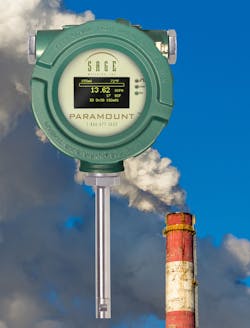
The key to compliance with both the Californian and National protocols is accurate measurements and emissions monitoring. The thermal mass flow meter (TMFM) emerged as the most effective technology to measure and report emissions. There are several reasons for this meter style’s popularity:
1. The TMFM has a very wide turndown and can thus cover flow rates over a 100 to 1 range.
2. The TMFM has excellent low-end sensitivity and can discern very low flow rates, typical of digester gas or biogas.
3. The TMFM measures mass flow rate and consumption without the need for ancillary temperature and pressure devices. Since the regulations require measurements of metric tons of emissions, directly measuring mass flow without the additional cost and installation of other transmitters is a significant advantage.
4. The TMFM has no moving parts (unlike turbine meters or Roots meters), thus eliminating the need for scheduled removal for maintenance or eventual replacement (it is not necessary to cut the pipe to install a flow section).
5. TMFMs are highly accurate and have extraordinary repeatability and reproducibility, critical to meeting the accuracy requirements of the protocols.
6. Most digester gas systems have pipe sizes typically 1-1/2" to 4," and an insertion-style TMFM is easy to install (particularly when using the manufacturer's mounting hardware).
7. The TMFM has negligible pressure drop (unlike all other gas flow technologies).
8. TMFMs have an easy-to-read display of mass flow rate and totalized mass flow. They also have convenient analog outputs and digital outputs that can log and report the emissions (e.g., report the quantity of methane destruction). Thus, for example, in a farm-based digester project, the amount of methane destruction can be measured and the associated reduction in greenhouse gas emissions can be determined.
9. Many TMFM manufacturers calibrate the flow meters with the specified gas mix in a NIST traceable facility and offer a means to validate that the flow meter retains its accuracy (i.e., it hasn’t drifted or shifted since the original calibration). This in-situ calibration verification can be easily performed in the field by the owner or operator of the project.
10. A TMFMs ability to verify its accuracy is critical to meet the protocol’s reporting requirements. There are penalties if quarterly or annual inspections by regulators (or reported by the project holders) show any loss of accuracy from the required specifications.
Canada to reduce methane emissions from oil and gas operations
The Canadian government is committed to tackling climate change by working primarily with Alberta, British Columbia, and Saskatchewan provinces. Recently, new, more strengthened provincial methane regulations, known as equivalency agreements, were finalized. The agreements represent a flexible approach for each Province to design methane regulations to reduce greenhouse gases that best suits their respective jurisdictions. Funding for this effort amounts to a $750 million Emissions Reduction Fund, and interested parties can apply through the Natural Resources Canada website.
An example of such a funded approach to reduce greenhouse gas emissions is replacing fossil fuel that typically operates valves in the oil and gas industry with compressed air. Since compressed air is “clean” (other than the cost to pump it), it eliminates the risk of wasting fuel through leaks or flaring. However, to quantify the reduction in greenhouse gas emissions versus fossil fuel, thermal mass flow meters are being used to monitor compressed air consumption. The convenience of thermal mass flow meters, with their built-in totalizing function, wide turndown, ease of installation and direct mass flow output (without the need for separate temperature or pressure transmitters), is highly desirable and the instrument of choice for this application.
Conclusion
It is hard to ignore the effects of climate change. Severe droughts, more frequent and intense forest fires, rising sea levels, record-breaking temperatures and more severe hurricanes are becoming the norm. As the planet warms, these events continue and become more extreme.
Although carbon dioxide makes up more than 70% of the greenhouse gas emissions worldwide, and methane only 20%, we cannot ignore methane emissions. With methane being 25 times as potent at trapping heat in the atmosphere as carbon dioxide, reducing methane emissions becomes a critical strategy to mitigate the effects of global warming and slow down the associated increase in the average global temperature of the planet (which already has risen over 1.1°C above pre-industrial levels).
There are numerous strategies to reduce methane emissions related to human activities, and prioritizing the most significant is critical. The largest source of methane emissions is the natural fermentation of livestock digestion and other agricultural-related activities. Distribution, transmission and storage of fossil fuels are secondary sources of methane emissions, with landfill and manure management being the third priority.
Targeting these sources and accurately measuring and monitoring the emissions is necessary to determine whether we reach our objectives. The thermal mass flow meter has emerged as the most effective gas measurement technology for these applications, featuring ease of installation, accurate and repeatable direct mass flow measurement, wide turndown and built-in software verification for protocol compliance. Their ability to perform with extremely low flow (low velocity), typical of biogas and landfill gas, and the standard venting, or the extremely high flow (high velocity) associated with flare gas's upset conditions, is unique to the technology.
Bob Steinberg is the founder, president, and CEO of Sage Metering. He is the author of An Industry Guide for the Use of Thermal Mass Flow Meters: Oil & Gas Production, Waste Management, Steel. Steinberg has over 40 years of instrumentation experience. Before forming Sage Metering in 2002, he managed thermal mass flow meter sales at Kurz Instruments, Sierra Instruments, and Eldridge Products. While at Weston Instruments, Steinberg was a product marketing engineer. He has a BSEE and a BA from Rutgers University. SageMetering.com
References
Enteric fermentation | Climate & Clean Air Coalition. https://www.ccacoalition.org/en/activity/enteric-fermentation
Government of Canada working with provinces to reduce .... https://www.canada.ca/en/environment-climate-change/news/2020/11/government-of-canada-working-with-provinces-to-reduce-methane-emissions-from-oil-and-gas-operations.html
Inventory of U.S. Greenhouse Gas Emissions and Sinks: 1990 .... https://www.epa.gov/sites/production/files/2019-04/documents/us-ghg-inventory-2019-chapter-executive-summary.pdf
Natural Gas Flaring and Venting: State and Federal .... https://www.energy.gov/sites/prod/files/2019/08/f65/Natural%20Gas%20Flaring%20and%20Venting%20Report.pdf
Greenhouse Gas Emissions Monitoring Using Thermal Mass .... https://sagemetering.com/pdf/GreenhouseGasEmissionsMonitoringUsingTMFMs-LowRes%28Rev2%29.pdf
Bob Steinberg
Bob Steinberg is the founder, president and CEO of Sage Metering. He has over 40 years of instrumentation experience. Before forming Sage Metering in 2002, he managed thermal mass flowmeter sales at Kurz Instruments, Sierra Instruments, and Eldridge Products. While at Weston Instruments, he was a product marketing engineer. He has a BSEE and a BA from Rutgers University.


