An overview of thermal mass flow sensors and applications
Mass flow controllers (MFCs) are devices that precisely control the flow of gases or liquids in a process or system. They are commonly used in a variety of industries, including chemical processing, pharmaceuticals and semiconductor manufacturing, to ensure that the correct amount of material is dispensed and to maintain process control.
There are two main types of MFCs: gas mass flow controllers and liquid mass flow controllers. Gas MFCs are used to control the flow of gases, such as air, nitrogen or oxygen, while liquid MFCs are used to control the flow of liquids, such as water, acids or bases.
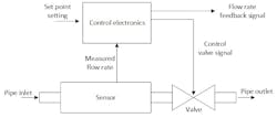
The basic structure of any gas or liquid MFC device consists of three elements: the sensor, the valve and the controller (see Figure 1). The MFC devices rely on the sensor to measure an output current or voltage proportional to the mass flow rate of the material being dispensed and use a control valve to adjust the flow rate to the desired level. They typically have a flow rate range, an accuracy level and a response time, which are all important factors to consider when selecting an MFC for a specific application.
Thermal mass flow devices are a sub-category of gas mass flow devices based on the kinetics of heat transfer in a fluid stream. The main physical characteristic exploited in this case is the specific heat capacity of the gas, which is the amount of energy that could be stored per unit mass of the gas. When the gas flows close to a heating source (resistance), it withdraws by convection the heat proportionally to the flow rate.
Hot wire anemometers were the first sensors that exploited this principle. They have evolved along the years into different designs and different packaged compact sensors with more or less embedded electronics. Thermal mass flow devices are particularly gaining acceptance by different markets as they produce an output signal that can be used in automatic measurement and control applications which is an advantage over the classical volumetric flow measurement principles (rotameters, venturi or orifice plate meters). They also have a large turndown sometimes reaching up to 200:1 with good accuracy (up to ± 0.1% F.S.) and repeatability (up to ± 0.1 % O.R.) levels.
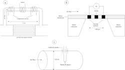
When it comes to a choice of thermal mass flow devices, the sensor technology used is of utmost importance. Three main different types are generally used (see Figure 2):
a) Capillary sensors (no contact with the gas)
b) MEMS or CMOS sensors (contact with the gas)
c) Inline or insertion sensors (contact with the gas)
Capillary sensors and MEMS (micro-electro-mechanical sensors) sensors both use a by-pass channel and a laminar flow element. The flow rate in the main gas path is deduced from the flow rate measured in the by-pass. The capillary sensors are called indirect gas sensors as the sensing elements (heater and coil) are not in direct contact with the fluid in contrary to MEMS sensors. MEMS rely on silicon chip technology where the micro size thermopiles (heater and resistors) serve as the sensing elements. The inline or insertion sensors are generally based on a pair of conductive probes placed in direct contact with the main stream.
Each technology has advantages and limitations that could have an impact on the choice of the suitable device for the specific request of the customer. The details regarding the design and the performance of the sensor are generally only known by the manufacturer.
For example, the use of MEMS/CMOS sensors usually require a real gas calibration at different points in order to reach the accuracy stated in the datasheet because of the non-linearity of the sensor on the whole flow rate range. It is yet possible to deduce conversion factors from the calibration gas to the application gas but this involves running tests on both gases at the customer pressure and temperature application, and at different points spanning the desired flow rate range, which is often expensive and tedious. A general way to overcome this nowadays is to store different calibration curves for different operating gases in the same device. Nevertheless, MEMS sensors show a better response time (in the order of ms) and a better sensitivity due to miniaturization and direct contact with the gas, which allows for a fast control of flow rate in applications requiring quick gas dosing for example. The micrometric size of those sensors involve also the miniaturization of the channel where the gas is flowing. This is reached by diverting part of the main flow in a by-pass channel of few hundred micrometers in diameter where a constant range of small gas flow rates go through. Using MEMS sensors is particularly advantageous for very low flow rates (< 10 Nml/min, Nitrogen gas).
Capillary sensors are in contrary better in linearity than MEMS devices without being perfect though. They are usually preferred when using aggressive gases due to the possibility to choose the material in the capillary channel and also when regular real gas calibration is not possible. They are also used with gas mixtures where constituents of the mix may change according to the season or the source of supply. The conversion factors (usually obtained from Nitrogen reference gas) are deduced theoretically from a simple formula using gas known parameters such as heat capacity and density (in standard conditions). The operator has the possibility then to switch easily between gases through the PLC or the device display/software if they are fed in the same line for example. Other use cases of capillary sensor devices could be high purity applications like in semiconductor industry, where specific requirements for materials in contact with the gas should be respected. However, the separation between the resistance wires and the gas substance formed by the stainless steel wall tube slows down a bit the response time of the device and limits its use for certain applications requiring fast and precise control of the amount of gas dispensed. Both capillary and MEMS sensor devices use laminar flow elements in order to deduce the flow rate in the main channel and prevent disturbance of the measurement because of turbulent flow. The dimensioning and reproducibility of those elements is a key in lowering the measurement noise level.
In contrary to capillary and MEMS sensors, the inline thermal sensors allow to reach very high flow rates by inserting the probes directly in the pipe if the sensor is not already mounted in a defined manifold. Using such devices generally require turbulent flow conditions (which is usually the case with large gas flow in pipes) to avoid wrong measurement due to the velocity profile. The nominal flow rate attainable depends on the pipe size. As with MEMS technology, the use of inline sensors result also in a nonlinear curve between the flow rate and the sensor output. The response is generally slow due to the thermal inertia of the probe, and the zero stability may be challenged because of natural convection becoming important at low flows. Depending on the flow rate range, typical devices with inline sensors are used with large pipe sizes starting from 1/2" in diameter up to 20" and where Vortex or orifice plates have been traditionally used. Example of applications are chemical engineering and processing technology, nitrogen or oxygen measurement for large utility plant and compressed air in environmental facilities or hospitals.
In general, and whatever is the sensor technology, care must be taken regarding the nature of the gas (some gases may decompose in contact with the heating elements and adsorb on surfaces), its humidity, and its purity (presence of particles). The user should check very carefully with the manufacturer for possible problems.
In summary, the sensors remain a strategical part of the MFM/MFC devices; some manufacturers may choose to focus on one technology while others would offer all possibilities. This depends on the business development model of the company and the markets where it historically operates.
Dr. Chakib Ouali is a product consultant and manager at Bürkert, one of the world's leading manufacturers of measurement and control systems for liquids and gases. He is currently managing the life cycle of sensor devices and also advising salespeople and customers on the field. Dr.Ouali holds a Ph.D. in Physics from Sorbonne University and a master degree in Physical-chemistry from ESPCI.
About the Author
Dr. Chakib Ouali
Product consultant and manager at Bürkert
Dr. Chakib Ouali is a product consultant and manager at Bürkert, one of the world's leading manufacturers of measurement and control systems for liquids and gases. He is currently managing the life cycle of sensor devices and also advising salespeople and customers on the field. Dr. Chakib OUALI holds a Ph.D. in Physics from Sorbonne University and a master degree in Physical-chemistry from ESPCI.


