This is NOT your grandfather’s orifice plate flowmeter
Key Highlights
- Proper installation, including adequate straight run piping and adherence to standards, is crucial for accurate flow measurement with orifice plates.
- Proprietary orifice flow measurement systems can reduce costs and installation complexity while maintaining high accuracy, especially in industrial settings.
- Regular inspection and maintenance of orifice plates are essential to mitigate wear, corrosion and deformation, ensuring sustained measurement precision.

Technology and everyday life were very different a century ago when most houses did not have running water or electricity, bathrooms were just being incorporated into building codes for new structures, sewage went largely untreated, telephone service was expanding, radio was a new form of communication, car ownership was in its infancy, most households had to transport fuel for heating and cooking, and fetch water for drinking and bathing. Shockingly, approximately 20 percent of children died before their 5th birthday, which was a marked improvement from a century earlier when over 40 percent died. The widespread adoption of highways, television, air travel, credit cards, space travel, antibiotics and other life-saving pharmaceuticals, computers, cell phones, digital streaming, CAT scans, pollution control, heart transplants, internet communications and many other conveniences came later.
The contrast between everyday living environments in the past and present can be experienced first-hand by contrasting the musty, drab, poorly lit, sparsely decorated rustic rooms serving multiple functions in historic buildings that truly depict the era, with their clean, modern, brightly lit modern 21st century bathroom often located in the same building, ostensively to shield visitors from the perils of period outhouses.
Similarly, science was less developed prior to the last 100 years of rapid technological innovation, and it was in this environment that the fundamental development for orifice plate flowmeters was conceived, data collected, then analyzed, and quantified.
Differential pressure flowmeter theory
Differential pressure flow measurement is based on Bernoulli’s Theorem which states that kinetic and potential energy are conserved across the flowmeter. The volume of liquid flowing through a differential pressure flowmeter operating in the turbulent flow regime can be calculated as: Flow Volume = constant x discharge coefficient x (pressure drop / fluid density) ½
Gas calculations are more complex but still contain the same square root relationship that introduces differential pressure measurement errors at low flow rates when the transmitter operates low in its range where flow rate accuracy is significantly degraded. For example, 10 percent flow produces only 1 percent of the differential pressure produced at 100 percent flow, and is measured with degraded flow accuracy. However, this can be mitigated by installing an additional transmitter with a lower differential pressure range to accurately measure low differential pressures, thereby increasing flowmeter turndown.
Linear flowmeters that measure velocity or volume, such as magnetic, positive displacement, turbine, ultrasonic and vortex shedding flowmeters, are inversely affected by changing fluid density. For example, increasing the density of the fluid flowing through these flowmeters by 1% causes the same amount of fluid to measure low by 1%. Differential pressure flowmeters with square root relationships are inherently superior in this regard because they exhibit approximately half of this effect. When superior accuracy is required, flow measurement errors caused by density changes can be reduced by compensating for the measured flowing density or inferred density from surrogate properties such as pressure, temperature and composition.
Experimentation performed a century ago revealed that the discharge coefficient in the turbulent flow regime is not constant, but rather a function of Reynolds number, which itself is affected by the flow rate, density and viscosity, where density and viscosity are affected by temperature. In contrast, the flowing volume in the laminar flow regime is inversely proportional to viscosity, and undetermined in the transitional flow regime. Stated succinctly, the underlying issue with this approach is that the discharge coefficient is affected by viscosity and Reynolds number.
However, the century-old paradigm of using differential pressure flowmeters to infer flow volume has reportedly been broken by the development of an energy correlation calculation derived from the equivalence of potential and kinetic energy changes that occur as the fluid flows through the restriction.
Mass Flow = constant x (pressure drop x fluid density) ½
This equation can effectively transform a differential pressure flowmeter that infers the flowing volume into a flowmeter that infers mass using simpler calculations that do not include compensation for Reynolds number. Fluid density is in the numerator, so its effect is opposite that of the flow volume measurement. When viscosity effects can be neglected, energy correlation calculations enable applications that previously would not have been considered, such as operation in the transitional and laminar flow regimes.
Flowmeter applications
Flowmeters typically fall into one of the following general applications.
Flow laboratory measurements and custody transfer measurements involve specialized measurements that generally require the highest accuracy, so particular attention is usually paid to details that can affect these flow measurements. Less important process control and monitoring flowmeters usually dwarf the number of raw material feed flowmeters in industry, so industry generally pays less attention to flow measurement system details.
Warning: Considerable friction can occur when the world of flow laboratories and custody transfer intersects with the world of industry. Trust me.
Some years ago, my mentor suggested that approximately 1 percent of flowmeter users who do not work in flow laboratories or with custody transfer are knowledgeable about flow measurement. Anecdotally, approximately half of my students, most of which had over 5 years of instrumentation experience, acknowledged having heard of Reynolds number. However, only a few students (excluding chemical engineers) meekly raised their hands to acknowledge knowing what Reynolds number is. Similarly, most of my students initially agreed that orifice plate flowmeters are simple devices, but virtually all disagreed after my presentation. These are not trick questions. They are fundamental to flow measurement. Just because an individual has selected, sized, specified and installed flowmeters for decades does not mean that the individual understands flow measurement. Given this context, it would be understandable for this article to discuss aspects of flow measurement that many readers may not have previously considered.
Straight run
Accurate differential pressure flow measurement requires a steady, homogeneous (single phase), fully developed, non-pulsating, non-swirling velocity profile entering the primary flow element. Good velocity profiles are typically achieved by installing the primary element in a straight run consisting of an upstream straight pipe section and a shorter downstream straight pipe section. The minimum lengths to achieve the stated uncertainty in certain piping configurations upstream of the straight run were determined by experimentation and published in standards or manufacturer literature. Upstream flow conditioners can result in shorter straight run requirements.
In some pipe configurations, upstream and downstream straight run requirements in the standards can be over 50 D and 15 D, respectively. Straight run requirements shorter than 10D/5D are generally not encountered in real world applications. Therefore, installations that follow the 10D/5D myth (masquerading as a rule-of-thumb) will work with inferior flowmeter accuracy, but suggest a design based on a limited knowledge of flow measurement and an increased potential for the presence of other flowmeter, instrumentation and control issues.
A differential pressure flowmeter measurement system consists of its upstream straight run, upstream flange and gasket, primary flow element, downstream flange and gasket, and downstream straight run. Therefore, the flowmeter effectively starts at the inlet of the upstream straight run and ends at the outlet of the downstream straight run.
Differential pressure flowmeter standards specify tolerances for the circularity, cylindricality and roughness of the entire straight run piping, which are especially stringent within a few diameters immediately upstream and downstream of the primary flow element. The piping should be clean, free from pitting, deposits and encrustations within a few diameters of the primary flow element. Grooves, scoring, pits, ridges resulting from seams, distortion caused by welding, offsets and the like, are not permitted. The maximum roughness of the straight run pipes is also specified. Stated differently, straight run piping is not just two pieces of generic straight pipe that are field-welded to flanges, between which the primary is sandwiched using whatever gasket is available. In operation, foreign objects, deposits, fouling and the presence of undesired solids or gas in the straight run can affect flowmeter geometry and degrade measurement.
Primary differential pressure flowmeter elements in flow calibration laboratory and custody transfer differential installations are generally fabricated and installed in conformance with standards. In contrast, industrial users often violate straight length standards and almost always install these flowmeters between field-welded pipe that is readily available onsite and does not conform to standards.
Orifice plate primary flow elements
Many orifice plate geometries were developed to handle various flow measurement applications, including conical for low Reynolds numbers, eccentric for liquid with some gas and gas with some liquid, integral to measure low flows, quadrant for low Reynolds number and segmental for liquid with some gas and gas with some liquid. These geometries are not used often because they generally exhibit inferior performance due to limited testing data, or because other flowmeter technologies can provide superior measurement.
Commonly used thin, concentric, square-edged orifice plates, used for both custody transfer and industrial flow measurement installations, are fabricated based on national and international standards. The standards generally describe the requirements to achieve a specified performance, including orifice plate manufacture, upstream and downstream straight run, tap location, orifice centering, pipe circularity, pipe cylindricality and pipe roughness.
In general, flow laboratory and custody transfer orifice plate installations tend to comply with these requirements to achieve the 0.5% discharge coefficient uncertainty cited in the standards. Periodic orifice plate inspection for damage helps maintain accuracy. The uncertainty associated with entire flow measurement systems will be somewhat higher when other sources of error, such as transmitter accuracy and fluid property uncertainty, are considered.
In contrast, industrial users usually purchase orifice plates that are machined in conformance to a standard, usually have correct tap locations, sometimes comply with straight run requirements and generally ignore the other requirements. This approach can be pragmatic in industry because conforming to all the requirements in the standards can be exceedingly expensive when only a reasonable flow measurement is needed. As a result of these compromises, industrial installations typically achieve 1-2% and 3-5% flow accuracy for liquids and gases, respectively.
However, some proprietary orifice geometries can perform as well as cited in custody transfer standards while relaxing the need for various requirements described in the standards. Therefore, they can often provide accurate flow measurements more economically. Stated differently, these designs enable more economical flow laboratory and custody transfer installations while potentially enabling industrial users to obtain close to custody transfer performance without paying for, or being knowledgeable about, the various requirements in the standards.
Orifice plate and gasket alignment
Standards specify that the orifice plate is centered in the pipe, and that its centering be measured. Gaskets shall not protrude inside the pipe, which can alter the geometry of the straight run. As a practical matter, full-face gaskets matching the inside pipe diameter of the straight run are suggested. In addition, the upstream and downstream bores are required to be matched and their flanges aligned.
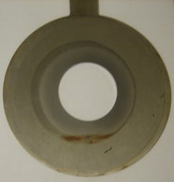
The orifice plates in Figure 1 and Figure 2 were removed from service after more than a decade of operation in industry between orifice flanges that were welded to their upstream and downstream pipes in the field. Discolorations indicate that none of the gaskets were centered. Wear patterns show that none of the orifice plates in Figure 2 were centered in the pipe. Further, the drain/weep hole was covered by the gasket in the leftmost orifice plate, rendering the hole useless. The rightmost orifice plate with the improvised handle appears to have been fabricated from 1/16-inch-thick sheet metal, which does not conform to standards. These and other deficiencies are not uncommon in orifice plate flowmeter installations in industry.
Orifice plate pressure tap locations
The following table summarizes orifice plate pressure tap locations on the pipe wall arranged by distance from the orifice plate.
Vena contracta, radius and full flow taps are welded to the pipe wall within tolerances stated in the standards. However, corner and flange taps can be incorporated into more expensive orifice flanges when practical and economically reasonable, such as in pipe sizes of approximately 6-inch and under, where accurately welding pressure taps in the proper locations can be difficult.
In general, the greater dynamic forces present at tap locations closer to the orifice plate tend to insulate the measurement from forces entering the flowmeter from upstream disturbances. It should be noted that pressure taps located on the pipe wall measure at a single location and tend to exhibit flow noise due to normal disturbances in the flowing fluid.
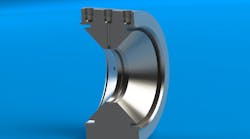
Figure 3 shows a proprietary orifice design that conditions the flow and senses pressures at the orifice bore, which eliminates the need for relatively expensive orifice flanges. These sensing locations exhibit stronger dynamic forces and provide more immunity to upstream disturbances, effects of misalignment and gasket issues, thereby reducing straight run requirements, further reducing the total flow measurement system cost. In addition, sensing pressure in annular slots tends to average the pressure over a larger area than sensing in pressure taps on the pipe wall, so measurements can be more stable and more accurate. The additional pressure tap can be used for diagnostic purposes.
Calibration
The overall concept behind a dry flowmeter calibration is that the flowmeter will measure accurately if it is manufactured, installed and adjusted in accordance with specifications in the standards. Stated differently, these are inferential flowmeters that should measure accurately but have not been challenged with fluid to ensure accurate measurement.
In contrast, wet calibration involves physically challenging the instrument with fluid and adjusting it to measure accurately. Specifically, wet flowmeter calibration is performed by adjusting the flowmeter to ensure that the amount of fluid measured by the flowmeter during a time interval compares favorably with the actual amount of fluid that flowed through the flowmeter at that same time.
Wet calibrating an orifice plate entails flowing fluid through the entire flow measurement system, that is, the orifice plate, transmitter and entire straight run. It is expensive to construct an entire orifice plate flow measurement system and transport it to a flow laboratory and then to the field for installation. Therefore, virtually no orifice plate flowmeter systems are wet calibrated, so virtually all are inferential flowmeters. That said, it is common practice to wet calibrate differential pressure transmitters with actual differential pressure inputs.
Repeating, most orifice plate flowmeters are dry calibrated, where accuracy is assured by manufacturing and installing the flowmeter in conformance with applicable standards. Specifications in standards are generally followed in flow laboratory and custody transfer installations. However, virtually no orifice plate flowmeters in industry are in conformance with standards because the various requirements are either not identified or deemed impractical.
Proprietary orifice flow measurement systems designed to have short straight run requirements are not only less expensive to manufacture but also less expensive to wet calibrate. For example, accurate measurement through a 6-inch orifice plate with a beta ratio of 0.60 installed downstream of a single 90-degree elbow would require a straight run of 42D/7D, or approximately 25 feet (7.6 meters) of piping, which is cumbersome and expensive to wet calibrate. In contrast, a proprietary orifice flow measurement system requiring a shorter straight run of 5D/3D, or approximately 4 feet (1.2 meters) of piping, would be less expensive to manufacture, and increase the viability of performing a wet calibration.
Wear and damage
The bore, sharp edges and flat surfaces orifice plates are subject to wear in normal use, so orifice plates in flow laboratories and custody transfer are often periodically removed and inspected for wear and damage, especially at their sharp upstream edge. Extraction devices are often permanently installed in the pipe to remove and reinsert orifice plates under operating conditions without depressurizing the pipe. In contrast, orifice plates in industry are typically inspected as a last resort after the flowmeter visibly measures in error, and after issues with the differential pressure transmitter and impulse tubing are ruled out.
In addition, orifice plates are relatively thin and therefore susceptible to various mechanisms that can alter their geometry and degrade measurement, some of which include:
- Deformation, such as caused by condensate in steam pipes; high differential pressure spikes; and opening and closing valves
- Corrosion
- Abrasion
- Cavitation
The proprietary orifice shown in Figure 3 is designed with a beveled (instead of sharp) front edge to mitigate wear, sufficient thickness to mitigate deformation concerns and can be specified with materials of construction that mitigate corrosion, abrasion and cavitation damage. Further, when designed using energy correlation calculations, the mass flow measurement is affected by approximately 2 times the change in the bore cross-sectional area. This means that a major erosion or deposit that changes the cross-sectional area by (say) 0.1% will affect the mass flow measurement by only 0.2%.
Installation
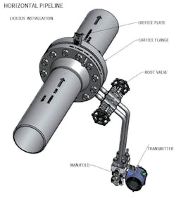
Figure 4 depicts a typical orifice plate flowmeter installation for liquid service in a horizontal pipe. The installation may appear to be straightforward, but it includes multiple components to include the upstream and downstream straight runs (shown in part), orifice plate, orifice flanges, gaskets, differential pressure transmitter, root valves, pipe fittings and impulse tubing that need to be specified, purchased, received and transported to the installation site for assembly, which involves a significant amount of field labor.
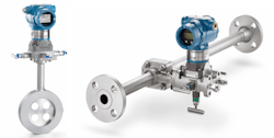
Various manufacturers offer proprietary one-piece orifice differential pressure flowmeter designs consisting of a differential pressure transmitter that is supported by the primary flow element, such as shown in Figure 5. This can simplify design, make installation easier and reduce the probability of installation errors. Depending on size, the cost of an installed one-piece differential pressure flowmeter assembly can be competitive with engineering, purchasing, performing logistics and applying field labor to install the individual components in industry. When sufficient accuracy for flow laboratory and custody transfer applications can be achieved, flow measurement system costs can be significantly lower when straight run requirements are significantly shorter than those specified in the standards.
Summary
Energy correlation calculations reportedly enable differential pressure flowmeters (independent of geometry) that measure flowing volume inferentially, to measure mass flow, independent of viscosity and Reynolds number, thereby enabling the use of simpler calculations in a wider range of applications.
The square root nature of differential pressure flowmeters enables them to exhibit approximately half the sensitivity to density changes as compared to linear flowmeters. It also produces low differential pressures at low flow rates, degrading measurement accuracy under these operating conditions. However, this can be mitigated by installing an additional low-range transmitter when more accurate measurement is required.
Orifice plate flow measurement systems have various disadvantages, including:
- Inferential measurement of flow volume
- Long straight runs with stringent piping specifications
- Sensitivity to alignment
- Impracticality of wet calibration
- Sensitivity to wear and damage
- Multi-component construction
One-piece proprietary orifice primary flow elements largely mitigate these disadvantages while being relatively easy to specify and install.
References
Global Climate Change: A Clear Explanation and Pathway to Mitigation, Chapter 4: Transition from a ‘Life of Death’ to a ‘Life of Life’, David W Spitzer, 2024 (available on Amazon.com)
Industrial Flow Measurement, Third Edition, David W Spitzer, ISA Press, 2005
Flow Measurement, David W Spitzer, Editor, Second Edition, ISA Press, 2001
Flow Measurement Engineering Handbook, Richard W Miller, Second Edition, McGraw-Hill, 1989
Fundamentals of Flow Measurement, Joseph P DeCarlo, ISA Press, 1984
Measurement of Fluid Flow in Pipes Using Orifice, Nozzle, and Venturi, MFC-3M, ASME, 2004
Measurement of fluid flow by means of pressure differential devices inserted in circular cross-section conduits running full - Part 1: General principles and requirements, ISO 5167-1, 2003
Measurement of fluid flow by means of pressure differential devices inserted in circular cross-section conduits running full - Part 2: Orifice plates, ISO 5167-2, 2003
Energy Correlation Flow Meters, Patent US 2023/0119021 A1, Zaki Din Husain, 20 April 2023
About the Author
David W. Spitzer
David W Spitzer’s new book Global Climate Change: A Clear Explanation and Pathway to Mitigation (Amazon.com) adds to his over 500 technical articles and 10 books on flow measurement, instrumentation, process control and variable speed drives. David offers consulting services and keynote speeches, writes/edits white papers, presents seminars, and provides expert witness services at Spitzer and Boyes LLC (spitzerandboyes.com or +1.845.623.1830).


