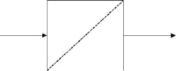
Filtration is the recovery of a material that is either wanted for reuse or unwanted and needs to be withdrawn from the system. Filters, in their most basic sense, are used to achieve selective recovery of a certain component or compound from a mixture. This recovery is accomplished when the material passes through a filter medium.
The driving force across the medium could be the differential pressure between the medium or gravity or even the concentration. However, there are factors, such as the operating mechanism of the system, the nature of the material being handled, the size of the filter medium, the operating condition (cycle, temperature, flowrate, etc.), and hydraulic properties of the fluid, which influence the process. The choice of filter media is often very important, as factors such as minimum propensity to bleed (the ability to create a solid bridge across its pores), minimum propensity to blind (the wedging of solids between the interstices of the pores), the minimum resistance to flow of filtrate, corrosion resistance, and resistance to mechanical wear, etc.
Filters can be classified by their characteristic applications (air filters, oil filters, flush filters, sand filters, etc.), by their operational provisions (rotary vacuum filters), or by design principle (cake, gravity, pressure, etc.). Cake filters accumulate appreciable visible quantities of filtered solids on the surface of the medium. Pressure filters do so under super-atmospheric pressure at the filtering surface. Whereas gravity filters operate at the available hydrostatic pressure of the fluid above it, hydraulic filters combine the principles of filters and the hydraulic press, etc.
The filter media are manufactured from cotton, polymers, asbestos, glass, cellulose, metals, fabrics, refractories, ceramics, sands, particulate solids, etc. Apart from the media, a filter aid may also be employed to improve filter performance, particularly when filtrate clarity is required.
No matter how big or small the filter, the basic principles of operation are the same. While instrument air filters are small in size and rotary vacuum filters are large, they both operate in the same fashion to get rid of impurities by passing the process fluid across a medium of special specification.
Filters are defined as equipment that is used to purify a material by a physical process in which the component responsible for the impurity is selectively trapped by filter media so that the filtrate can be recovered for use. Filters are used mostly for air, gas, oil, and liquid filtration. Sand filters are used for water treatment. Filters are typically located on instrument air lines to the process control valve, lube oil lines from lube oil pumps to the process, and the process stream lines, as well as on water treatment lines.
Proper Procedure for Filter Operation
Specific filter types are identified for each topic below, as covering all possible filter options is beyond the scope of this article. However, there are lessons to be learned from each of the following discussions that can be applied to other filter types.
? How to Commission Filter (flush filter)
? How to Divert Filter Flow (lube oil flush filter)
? How to Prepare the Filter for Maintenance (process filters)
? How to Approach Filter Design (fuel filters)
Most flush filters are used to provide clean flush liquid material for use in equipment that requires continuous flushing. Equipment is flushed so as to prevent the possible chemical effect of the process fluid on the equipment or its parts. Chemical corrosion is the typical attack normally encountered on the seal material used in pumps. Also, most flush material is either liquid paraffin or hydrocarbon of low viscosity, selectively designed to give a clean, clear wash. The following discussion is based on paraffin flush filters. A typical example could be found in use on acid pumps. To Commission a Flush Filter
Applying Filters at the Right Location
In many applications, fluid filtration plays an important role in extending the service life of system components. There are three major areas in a system where filters can be located. They are: Suction Line Filters, Return Line Filters, and Pressure Line Filters.
1. Suction Line Filters: Suction line filters are normally located at the suction line of a pump to protect the pump from particles that can damage and cause problems for downstream components. Such particles may come from debris in the supplying reservoir, rust as a result of corrosion of internal components. When a suction line filter is fine (e.g., low-micron rating of about 25 microns), it causes restriction to inlet flow, and this restriction increases as the filter clogs and at low fluid temperatures. If the filter is too fine, it creates a higher pressure drop than can be tolerated at the inlet line, typically resulting in cavitation. But a low-micron-rated filter can be applied if the pump is force-fed by another pump. It is advisable that suction line filters should have either a relatively coarse mesh filter or a very large fine mesh filter of about 150 microns. Suction line filters are generally an inexpensive filter option.
2. Return Line Filters: The return line is another location for filters. Return line filters are located on the return line just before the line enters the reservoir. This is to prevent generated or ingested contaminants from entering the reservoir. They are usually installed in systems that don’t have large reservoirs that enable debris to settle out of the fluid. These filters can be offered with ratings from 3-25 microns. But a common rating of 10 microns is typical.
Return line filters are capable of high filtering efficiency at an economical cost because they have sufficient pressure available to force the fluid through the filter media without collapsing the filter housing. This in combination with its very low velocity makes a return-line filter nearly a must in most systems.
3. Pressure Line Filters: Pressure line filters are usually located at the discharge of the pump and where system components, such as valves, have low dirt tolerance. This protects system components that are located immediately downstream of the pump, because they trap very fine particles from the fluid that leaves the pump. Pressure line filters usually have elements with 1-5 microns and have a beta ratio of above 50. Pressure line filters and their housings are designed to withstand full system pressure, and any cyclic pulses generated by variations in the pump operation. These requirements make pressure line filters more expensive than both the suction line filters and return line filters. Pressure line filters are generally limited in application due to their high initial and ongoing cost.
1. Confirm the filter is in good working condition.
2. Ensure the flush material is available to the filter.
3. Line up the filter in the flow line. The filter can be lined up in series or in parallel depending on the efficiency and operational provision.
4. Check to ensure the filter differential-pressure gauges tapped at the ends of the filters are in place and in good working condition. Filter differential is the parameter that describes the status of the filter at all times. In some instances, concentration changes, increases in the thickness of cake deposit, or even the conductive properties of filtrates are used as the driving force across filters.
5. Commission the filter by placing isolation valves between the filters. The flush filter downstream valve should be placed before the upstream valve so as to prevent the septum from damage due to pressure buildup. During shutdown, the reverse is the case.
6. Confirm the filter operating pressures and differential pressures are normal.
To Divert Filter Flow
In a lube oil and flush filter application where provisions are made for diversion due to poor filter performance, operators need to divert the process flow through the standby filter. To accommodate this diversion:
1. Place a valve downstream of the standby filter to be commissioned.
2. Close the upstream valve of the filter in service, and place the upstream valve of the standby filter simultaneously.
3. Close the valve downstream of the filter in service when its pressure dropped. Then completely shut it off by double blocking its isolation valve.
The above causes are mostly applicable to flush filters. Lube oil filters are provided with diversion arms that direct the settings of the flow through the filters. The arm is normally in the form of a handy valve built for that purpose. It is simply turned as described by design and labeled thereby. Operators should therefore be familiar with the diversion techniques labeled by the vendor.
To Prepare Filters for Maintenance
The following is based on the maintenance procedure for process filters, such as rotary vacuum filters, sand filters, and, to some extent, clay treaters. These are process equipment used directly in line, unlike flush oil and air filters used on process utilities.
1. Most importantly, make sure that the filter is isolated. Double blocking and spade blinding (used for positive isolation) is required when any hot work on the filter is necessary. Spading is recommended where flammable process fluids are employed.
2. Drain out any hydrocarbon to the close system.
3. Open the vent and air purge to the atmosphere. However, flammables are to be flared until no traces are noticed when work or entry is required.
4. Open the man ways and authorize entry when its safety is guaranteed.
These are only some of the basic maintenance preparation requirements for process filters found in diverse use.
Addendum
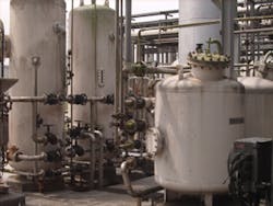
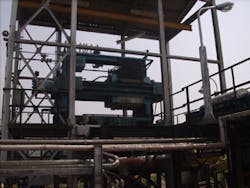
As noted earlier, there is a range of filter types in use in process plants. These filters are either small in size (instrument air filters), average in size (flush filters and lube oil filters), or large (sand filters and rotary vacuum filters). Users should review the operating procedure of all of their filters. Filter efficiency reduces the rate of cleaning and the frequency of switching of filters assembled in parallel during operations.
Chikezie Nwaoha previously completed a term as an operator (student trainee) with Port Harcourt Refining Company in Nigeria (PHRC, www.nnpcgroup.com/phrc.htm) and is currently working as a process engineer for Tranos Contracting Ltd. He is also in the process of conducting research for a book titled “Process Plant Equipment Operations and Control.” As part of his research, Mr. Nwaoha has authored over 25 engineering articles in leading international journals. He is a member of SPE, IMechE, ICE, IGEM and Nigerian Gas Association (NGA, www.nigeriangasassociation.org). He is also an ambassador for IMechE in Nigeria. He has a degree in Petroleum Engineering from the Federal University of Technology, Owerri, Nigeria. Mr. Nwaoha can be reached at [email protected], +234-703-135-3749.
www.tranoscontracting.com


