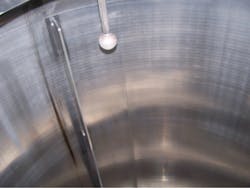
Spray balls are used in the pharmaceutical and food industries to facilitate the regular cleaning of tank and piping. They allow the tanks to be cleaned by dousing the interior surfaces with high-velocity jets of hot water and/or chemicals. This process is called Clean-In-Place or CIP.
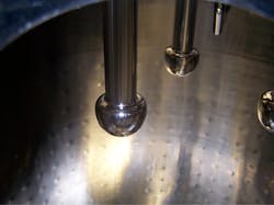
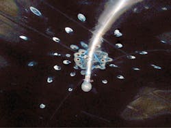
Spray balls come in many shapes and sizes and have various functions. One type, a fixed-spherical spray ball design, is pictured in Figure 1. This particular spray ball is a permanent static mount, designed to direct multiple high-velocity jets against the tank wall. Some spray balls are thick-walled to allow each drilled hole to become a very efficient cleaning jet. Another design is thin-walled to allow each hole to act as a divergent spray. There are mushroom-shaped balls that provide room for more holes to be directed upward to clean overhead surfaces like those illustrated in Figure 2. Spray balls may be fixed or detachable. Some are dynamic so they rotate; others just spray the cleaning solutions where they are designed to spray. The hole pattern and diameter are usually specific for the system being cleaned. The hole pattern allows 360-degree coverage, 180-degree upward spray, 180-degree downward spray or 270-degree spray. Type 316L stainless steel is the most common material of construction. Most have an electropolished surface that is smoother than 20 Ra (0.5 μ).
Clean-In-Place
What is Clean-In-Place or, as more commonly called, CIP? It is the use of special disinfectants, hot water and/or steam to kill bacterial organisms that may affect the product. Use of steam usually is referred to as Sterilize or Sanitization-In-Place or SIP. Both are highly efficient processes that can be automated and designed to provide maximum coverage. Spray balls make this possible. There are five factors to be considered in the cleaning process: temperature, time, required chemicals, pressure, and the coverage by the spray balls. Once the cleaning cycle parameters are defined the entire process can be automated.
The process must be designed to clean thoroughly and in a timeframe that allows optimum production. Therefore, the cleaning cycle is usually designed to be more efficient than is perhaps necessary with greater volumes of solution at higher velocities.
Water for injection
Pharmaceutical plants use huge quantities of pure water. Two basic grades of water are used: Purified Water and Water for Injection. Purified Water is used for non-injectable applications and products that do not contact blood. It must be biologically and chemically pure so neither undesirable chemicals nor harmful bacteria are introduced into or onto the body. Water for Injection, or WFI, is the next step up in product purity. It must meet the same chemical requirements as Purified Water, but in addition must meet the highest requirements for being free from bacterial contamination. WFI is used wherever the water directly enters the bloodstream. This water quality must meet the requirements of the United States Pharmacopeial Convention (USP), which defines the purity levels that the industry must meet. Superimposed on this is FDA guidelines and requirements.
This standard results in water with a specific conductivity of less than 1.25 μS/cm, making water almost completely devoid of any ions whatsoever. Since water is nearly a universal solvent it is extremely reactive. This sets the stage for rouging to occur. Figure 2 shows the interior of a tank with mushroom head spray balls. Rouge streaks are visible along the walls and on the spray ball stems. The streaks appear to originate from the tank head.
What is rouge?
Rouge is iron oxide. It is usually red, but it can be yellow, reddish-brown, brown, blue or black. The color depends on the valence of the iron and the water of hydration in the oxide. (For a more detailed explanation see "Rouging of Stainless Steel: Why Good Stainless Steel Turns Red," Flow Control, March 2003, Page 181,2. An in-depth analysis is available in "Rouging of Stainless Steel in High Purity Water," ASM Handbook, Volume 13C, Page 15, 20063.)
Rouge may be categorized in three classes:
- Class 1 rouge is generated in an external source and is deposited on stainless steel surfaces throughout the system. In the early stages of deposition it is powdery red and can be easily wiped clean. The passive layer under the rouge is unchanged from the original passivated surface.
- Class 2 rouge is chemical corrosion of stainless steel. It develops when corrodents are present that can attack the passive layer. These include chlorides, chloramine, other halides and some organic acids like oxalic and formic. The rouge forms blisters or tubercles that cannot be easily removed except by grinding. The rouge is usually red with a rough surface. When the blisters are picked off there is bright silver stainless steel under them.
- Class 3 rouge is black or, when very thin, blue. It forms in situ in the presence of high-temperature steam. Chemically it is different from the red corrosion product, Fe3O4, and is called magnetite. It is very stable and if removed forms again in situ. For this reason it is best to leave it alone.
It is important to remember that Type 316L stainless steel is 70 percent iron. (For a better understanding of stainless steel and how it corrodes see the "Stainless Steel Primer" series that appeared in Flow Control, August, September, October 2000 4, 5, 6.) Any condition that destroys the passive layer on the stainless steel will result in oxidation of the iron according to the following equation:
2Fe0 + 4H2O → 2FeO(OH) + 3H2
2FeO(OH) → Fe2O3 + H2O
The Fe2O3 is the common red rust that is known as hematite. The passive layer is what gives stainless steel its corrosion resistance. It can be destroyed chemically or mechanically. Acid chlorides or other aggressive acids usually are responsible for the chemical destruction of the passive layer. This can result in red rust deposits. One common source of rouge is the residual polishing debris left inside the striations from mechanically polishing the interior of the tanks or tubing. Electropolishing dissolves this grinding dust so it cannot oxidize and redeposit as Class 1 red rouge.
The other source is erosion of the stainless steel surface by high-velocity water. This also results in Class 1 rouge. Two common sources are: centrifugal pumps and impingement areas from spray balls. Centrifugal pump erosion can come from the impeller tips exceeding the critical erosion velocity and cavitation. Cavitation erosion is common in hot water systems. Sometimes pumps will turn red from the hematite that is carried in the water and is plated out on the pump surfaces.
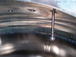
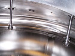
Spray-ball erosion is more subtle. First, the CIP cleaning systems usually are complex with many spray balls, numerous valves and lots of piping so people tend not to question the calculations. Second, the drilled holes, their pattern and the type of spray ball are the domain of the design engineer. Design of these systems is no easy task, especially calculating the impingement velocity for each jet. Some spray balls can have over 100 holes. This must be matched to the fluid balance determined by the hydraulic engineer. Because of the interdependency of so many variables and designers, and the fact that this has not been identified as a critical item, high velocities can slip by unnoticed — that is, until someone notes the impingement spots on the interior of tanks such as seen in Figures 3 and 4.
Spray ball erosion
Measuring the depth of the eroded spots shown in Figure 3 gave an average value of 0.010 inch and the average diameter of 1 inch. Fifty spots were identified on the dome of the vessel in Figure 3. The volume of metal eroded was calculated to be 0.375 in3. Because there were two spray balls in the tank the total volume of stainless steel removed was 0.75 in3. Keep in mind that this may not be the only system that sees these velocities. Since Type 316L stainless steel is 70 percent iron and Fe2O3 is 70 percent iron, there will be 0.75 in3 of rouge from these two spray balls. If the rouge thickness is 0.001-inch thick it will uniformly cover 5 square feet. The iron would be deposited as red rouge, but the chromium, nickel and molybdenum that are in the removed metal are soluble and may conceivably contaminate the product being produced, although in very minute amounts.
In this example the flow into the spray ball was 60 GPM or 0.134 ft3/sec. The spray ball had 110 holes 1 mm (0.039-in) diameter for a total of 0.000885 ft2. The tank had two spray balls so the hole area was 0.00177ft2. The velocity calculated by using the expression Q=AV resulted in an average water velocity of 75.7 ft/sec. The resulting spots are stripped of their passive layer and will continue to corrode until the system is repassivated.
The ASME Feedwater Heater Power Code (asme.org) cites a maximum velocity for hot water in stainless steel of 20 ft/sec. Based on the ASME values for safe operation, these spray balls are operating at nearly four times the maximum velocity.
Corrective action
If the spray ball holes were drilled to 2.0 mm (0.079 in) the velocity would be reduced to 18 ft/sec. This would be a safe velocity and should be more than adequate to clean the system.
In addition, this tank needs to be refinished. This involves grinding the eroded spots to remove all disturbed metal and polishing to a surface finish of 20 Ra (0.5 μ) and electropolishing the ground spots. Then the entire system must be de-rouged, followed by repassivation using citric acid with EDTA (ethylenediamine tetra acetic acid), an iron chelating agent. A word of caution concerning de-rouging: always use a reputable contractor; otherwise your tank may look like the one in Figure 5. In this example, the corrective action involved grinding the entire tank, electropolishing in situ, and replacing all piping, spray balls, valves, and pumps.
Changing the material of construction to an alloy with less iron, such as AL-6XN, 25-6Mo, C-22 or C-276, will result in less red rouge. These alloys are not more resistant to impingement erosion, but the particles will not form Class 1 red rouge.
In summary
Spray balls are an essential part of CIP systems. They can be a source of Class 1 rouge if the fluid velocity through the holes exceeds 20 ft/sec. If any areas of impingement erosion are discovered during examination of the vessels then it is an indication that the velocity is too high and remedial action must be taken.
References
1. "Rouging of Stainless Steel: Why Good Stainless Steel Turns Red," Flow Control, March 2003, Vol. IX, No. 3, Pages 18–24
2. "Get the Red Out – Stop Corrosion in Your Parts Washing Systems," CleanTech, April 2004, Volume 4, Number 4, Pages 22–26
3. "Rouging of Stainless Steel in High-Purity Water," Metals Handbook, Volume 13C, Corrosion, October 2006, American Society For Materials, Materials Park, Ohio
4. "A Stainless Steel Primer, Part 1: The Types of Stainless Steel," Flow Control, August 2000
5. "A Stainless Steel Primer, Part 2: Corrosion Mechanisms,” Flow Control, September 2000
6. "A Stainless Steel Primer, Part 3: Selection of the Proper Alloy," Flow Control, October 200
John Tverberg, principal in the firm Metals and Materials Consulting Engineers, holds bachelor’s and master’s degrees in Metallurgical Engineering and a minor in physical chemistry from the University of Arizona. He was an exchange scientist with EURATOM at Metallgesellschaft, Frankfurt, Germany. Mr. Tverberg is a licensed professional engineer, a Fellow of the ASME, and a member of ASME, ASM International, NACE, and ISPE. He may be contacted at 717 244-7120 or [email protected].

