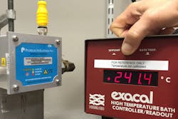
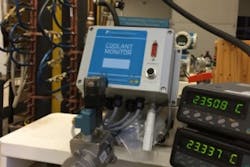
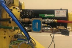
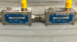
The original plan was to develop a flow measurement and control system with leak detection and energy-use calculations for liquid-cooled supercomputers at the Lawrence Livermore National Laboratory. The outcome included applications for military vehicles and other harsh environments, as well as calibration with liquid flow rates at temperatures from -80 C to 240 C.
3 original designs
For the semiconductor industry, a 200 C liquid flow rate sensor was planned and designed (see 200 C section on page SS-6.) For the automotive industry, a reduced size with vortex or paddlewheel-turbine sensors and one or two communications ports for Ethernet, Profinet, DeviceNet protocols were planned and designed (see WeldSaver section on page SS-5). For the fastest supercomputer at the time (2012), the Coolant Monitor was planned and designed with IBM, (see Coolant Monitor on this page).
A surprise phone call from the Army
Sometimes a phone call makes all the difference. One such phone call came from a deployed, mobile Army Missile Control Center. The outcome was the examination of the actual use of a product versus the published product specification. The result of the examination review was to create a harsh environment product specification and conduct a related test plan. The critical consideration was that the product was being used in an unintended application, and lives were potentially at stake. Obviously, there was a need for a product that didn’t exist and wasn’t specified. It wasn’t "build it and they will come," but rather, "they came, and we shall build it." A Mil-Std 810 Test Plan was developed and conducted. This activity had many lessons.
Lessons learned No. 1
One lesson is how to determine the testing requirements and achieve third-party verification. Because Mil-Std 810 is a general harsh environment document, one must choose the appropriate harsh environment of intended use to plan the testing.
Another lesson is that prime and subcontractors don’t always forward military specifications or requirements down the supply chain. Sometimes there is no specific military specification beyond the commercial-off-the-shelf manufacturer’s data sheet. As a lower-tier, down-chain supplier, sometimes there isn’t even a category for the intended supplier tier. As a consequence, one doesn’t always know where or how one’s product is being used.
Another lesson is how to cobble together information from various sources (military magazine articles, weapons advertisements, possible customers) to create a list of probable weapons systems similar to the vague description from the telephone call — i.e., a mobile Missile Control Center. In the end, we discussed possible test requirements with several laboratories specializing in military applications to create a harsh environment test plan for this product (though, one might think this was an intelligence-gathering operation, rather than a company trying to make a product).
The corollary lesson is that it is a process to get the specification correct and a process worth the effort because the product design and testing depend on it.
Coolant monitor
Liquid-cooled supercomputers don’t work well when wet or when the power source explodes because cooling fluid has leaked out. And, as things get more enclosed, electronics and everything else operates at ever-higher or colder temperatures and higher pressures. These more extreme temperatures cause premature failures in electronic, electrical and mechanical devices.
Figure 1. Supercomputer coolant manifolds (2 meters long) (Courtesy Ed Empaynado/Richard Fertell)
The IBM Sequoia Supercomputer was the fastest computer in the world for a few months in 2012. The liquid-cooled computer consisted of about 100 cabinets of multiblade parallel processors. During test runs of the first few cabinets, the processing rate was shy of the performance goals for speed and energy recovery. Upon further analysis, the coolant monitoring and control system was discovered not to be calibrated as used. The coolant monitor system liquid flow rate sensors (both vortex and differential pressure) were calibrated for straight-in plumbing and not with the turbulent-creating manifold with its many 90-degree bends (Figure 1).
These bends caused fluid swirling and pressure drops that impacted the flow technology sensing and thermal flow mass calculations that ultimately changed the temperature of each processor blade out of the optimum temperature range and slowed the computing.
A megaflop here and a megaflop there, soon add up and keep a supercomputer from the top of the list.
What’s more, the thermal mass flow accuracy impacted the energy recovery system operation, which will turn on or off based on the thermal content of the fluid. When a threshold of thermal content is passed, energy can be efficiently recaptured by using the transferred thermal heat to generate electricity through a heat exchanger process, which cools the fluid at the same time and reduces the new energy required to cool the heat transfer fluid that passes through the supercomputer.
To resolve the flow calibration issues, the actual supply and return manifolds used in the supercomputer cabinets were added to the flow sensor calibration system. Experiments determined the flow turbulence range corresponding to active/inactive blade configurations so that the flow sensor calibrations removed the turbulence effect and the rest is supercomputer history, as reported on Lawrence Livermore National Laboratory’s website.
Researchers at Lawrence Livermore National Laboratory have performed record simulations using all 1,572,864 cores of Sequoia, the largest supercomputer in the world. Sequoia, based on IBM BlueGene/Q architecture, is the first machine to exceed one million computational cores. It also is No. 2 on the list of the world’s fastest supercomputers, operating at 16.3 petaflops (16.3 quadrillion floating point operations per second).
The simulations are the largest particle-in-cell (PIC) code simulations by number of cores ever performed. PIC simulations are used extensively in plasma physics to model the motion of the charged particles, and the electromagnetic interactions between them, that make up ionized matter. High-performance computers such as Sequoia enable these codes to follow the simultaneous evolution of tens of billions to trillions of individual particles in highly complex systems. 1
Lessons learned No. 2
Calibrate flow sensors in setups and conditions as close to the real application as possible.
WeldSaver gets smaller & moves to robot arm
Robotic arm (Courtesy Mitch Yencha)
The automotive industry uses robotic welding machines that require fluid cooling at the welding contact tips (called caps) to maintain consistent quality welds. These contact tips are press-fit and sometimes come off when sticking to the work. The WeldSaver, with patented leak-detection technology, shuts off the coolant flow and outputs alarms to the robotic welding machine and other plant controls to stop the production line, until the contact tip is replaced and the "cap-off" condition is cleared.
WeldSaver developments focus on additional features, communication protocols, smaller sizes, different flow technologies and remote sensing, among other things. Welding cell and entire plant automation requires equipment communications. And different communications protocols are used by different companies. Welding processes can be better monitored and controlled at the closest location to the actual welding. Robotic welding arm movement is fast with abrupt stops, and changes in direction can create many G–Forces that stress mechanical and electronic components.
Continual improvements to the WeldSaver led to an opportunity to develop a coolant monitor.
Lessons learned No. 3
Continual product improvement keeps the product relevant to the industry. Continual product improvement opens doors to applications in other industries.
200 C liquid flow sensor
The supercomputer isn’t in the harsh environment of the portable Missile Control Center or the semiconductor fabrication equipment, where there are temperatures approaching 200 C and electromagnetic fields from motors, transformers, high-energy pulses, klystron or magnetron tubes, and clock and communication frequencies, as well as radiated energy from second-order through fifth-order harmonics.
An improved design was required for the flow instrument, as it could no longer be in a five-sided plastic enclosure that mounted
Figure 2. Submerged flow-sensing computers cycling through 5 C to 80 C (Courtesy Hamed Ershad)
the electronics PCBA (Printed Circuit Board Assembly) with microcontroller and magnetic field sensor directly to the fluid flow transducer. The fluid temperature approached 200 C and radiated into the electronics PCBA area. This 200 C temperature exceeded both the electronics components and magnetic flow sensor temperature specifications. The electronics PCBA and magnetic field sensor were moved into a six-sided metal box and mounted on the fluid flow transducer with an air gap and a film insulator plate. Flux concentrator rods redirected the fluid flow transducer magnetic field into the metal electronics enclosure so that the magnetic field sensor could detect the signal. The LED status indicator was retained for field troubleshooting, and the size of the view hole was shrunk to 0.0625" from 0.250". The 0.0625" hole was the largest gap in the stainless steel and effectively blocking electromagnetic wavelengths of frequencies to 188 GHz.
Figure 3. Hose down of more than 65 GPM at 1’ (Courtesy Hamed Ershad)
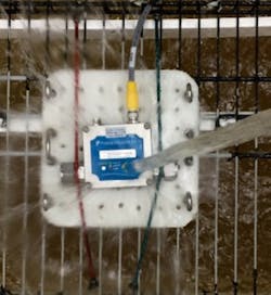
Immunity to electromagnetic interference and power field magnetic was tested to the limits of the third-party test laboratory’s equipment: 10 GHz at 10 V/m and 110/240 VAC at 400 amps. Operation with fluid temperature was tested with the fluid temperature run through the unit at 80 C and 240 C. To verify the impact resistance of the electronics enclosure, an 872-gram torpedo was dropped from 1.5 meters onto the electronics enclosure. Electronics enclosure seal strength was tested by placing the unit under water with fluid passing through the unit that cycled between 5 C and 80 C (Figure 2), as well as performing hose downs of 65-plus GPM from 1’ away of electronics enclosure seams (Figure 3) after the unit was temperature soaked to -40 C and 200 C. Through all of this harsh environment testing, the unit measured the flow rate properly, output flow control signals properly, and kept a cool head with the electronics components temperatures about 82 C at the maximum fluid and air temperatures. The two most satisfying technological findings were: 1) the microcontroller was not disrupted by the 10 GHz at 10 V/m EMI; and 2) the sensor magnetic field was not disrupted by the
Power Field Magnet from 110/240 VAC at 400 amps. The microcontroller protection to 188 GHz was predicted by standard electromagnetic wavelength to frequency calculations. But the imperviousness to the power field magnet when magnetic flux concentrators were used to direct the flow sensor magnetic field to the Hall-effect sensors was, to say the least, a big smile moment.
Performing flow calibrations outside 5 C to 90 C fluid temperature range
To setup an accredited calibration system at fluid temperature seemed easy — use master flowmeters that were calibrated at temperatures between -80 C and 200 C by an accredited lab. Unfortunately, there did not appear to be a flow lab that calibrated with traceable standards outside the 5 C to 90 C fluid temperature range. All calibrations were extrapolated for fluid temperatures outside of the 5 C to 90 C range. This surprise was verified at the ISFFM (International Symposium on Fluid Flow Measurement, www.isffm.org) 2015, in Arlington, Virginia, where Aaron Johnson, Ph.D., of NIST asked for comparisons of Coriolis flowmeters at flow temperatures to be made and published.
What’s more, the product firmware testing was accomplished using analog circuitry for monitoring the unit output signal and a crystal oscillator to input a precise test frequency. The test technician designed and built a 12-unit test fixture with two-colored LEDs in a latch-comparator circuit to indicate when the unit-under-test output signal exceeded the high or low tolerance values that could be adjusted to the tolerance value +/-0.0001 VDC.
Lessons learned No. 4
One should verify and not assume that the calibration flow sensor references used for temperatures or fluid properties in the application have actually been verified with traceable measurement uncertainty.
The Takeaway List
- The environmental specifications need to be passed through the supply chain, especially when COTS products are used in military applications; unless one wants a supplier to receive a surprise phone call from the battlefield.
- A test plan needs to be developed for the actual application environment with a minimum safety margin of 1.5 x rated operating; best practice is 1.5 x test or published absolute maximum.
- The test plan must to be followed. (2)
- With a detailed and application-environment-oriented specification and test plan, amazing supercomputers can be implemented, energy can be regenerated and lives can be saved.
- Just because a reference is calibrated by an accredited laboratory, the calibration may not match the actual application and the unit measurement uncertainty can be greatly altered.
- Sometimes, working on different things leads to insights and benefits for the other things.
References
- "Record Simulations Conducted at Lawrence Livermore Supercomputer," LLNL, www.llnl.gov/news/record-simulations-conducted-lawrence-livermore-supercomputer.
- "Follow the test plan!," Harry Schwab P.E., Test Engineering & Management, April/May 2015, Volume 77, Number 2, pp 6-7.
Richard Fertell, M.S.C.S., has 25 years’ experience as a flow measurement scientist at Proteus Industries Inc. He has presented papers on liquid flow rate at ISFFM, NCSLI, IMEKO, FLOMEKO, CFM and conducted flow measurement workshop tutorials (Liquid Flow Rate Fundamentals, Coriolis Meter Measurement Uncertainty Analysis, Liquid Flow Rig Measurement Uncertainty Analysis) at MSC (Measurement Science Conference). His book on flow rate measurement technologies and measurement uncertainty is being reviewed for publication as an ASME Standards Document. Fertell can be reached at [email protected].
