Editor’s note: In "Part I: Coriolis meter basics" (March issue, page 15), theory of operation, verification and calibration paradigms and techniques were discussed; an introduction was given to third-party agency/regulator recognition; and case studies were presented in which verification techniques identified meter damage and resulting accuracy issues.
Part II focuses on verification hypothesis testing — verifying the meter has not shifted, true damage detection, false alarms, covert failures, as well as third-party agency and regulator recognition. Areas of ongoing research and customer need are also discussed.
Verification tracks a secondary variable that is highly correlated to the flow measurement. Verification results are not generally traceable from a metrology perspective, although some vendors may claim this.
A two-by-two hypothesis testing matrix accounts for all results regardless of the variability of the test procedure and the variability of the unit under test. This hypothesis testing approach is used in fields such as as medicine, pharmacology, radar and target recognition. The same methodologies used there are also useful for understanding flow meter verification results.
Table 1. Verification hypothesis testing matrix. All graphics courtesy of Micro Motion Inc.
Table 1 shows a generalized hypothesis testing matrix as applied to flow meter verification. This table can be transposed and/or the rows and columns interchanged without affecting the underlying understanding.
Table 1 is presented with the rows of the matrix corresponding to the meter condition, such as if the meter is actually measuring within specification. The first row corresponds to a meter condition where the meter is reading flow accurately. The second row corresponds to a meter condition where the meter is reading outside the flow accuracy specification. The difference here is that the actual condition of the meter will not be known if no proving results exists.
These columns correspond to the verification result, pass or fail. The individual cells of the matrix represent the correlation between the condition of the meter and verification results. The point of presenting the hypothesis testing matrix is to show that the condition/accuracy of the meter can be determined probabilistically from only the meter verification result.
The Alberta Energy Regulator’s Directive 17 and other third-party agencies allow use of internal meter verification diagnostics to extend proving intervals for many Coriolis applications. This green light-red light approach suggested by Directive 17 may be all that is needed for many applications. Relying solely on the pass or fail results of the verification makes sense for many users. The interpretation of the results is left up to the software that is provided by the Coriolis manufacturer. Users should ask their Coriolis vendor(s) to discuss their verification technology, test results and experience with their product in similar applications. Ask the vendor for third-party data that shows the correlation between meter verification and flow meter accuracy.
If these discussions show that the pass/fail approach is suitable, the statistical discussion in the following section may not be as relevant for those users.
True positive outcome
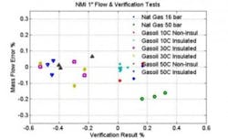
Figure 1. NMi Testing Mass Flow Accuracy vs. SMV results, 1-inch (25-milimeter) meter
The verification results presented in Figures 1 and 2 are a good example of what will be seen in a typical application. These results are true positive results because the verifications all passed and provings (calibrations) were completed at regular intervals that confirmed the meter was accurate.
In another round of third-party testing of direct stiffness measurement verification, NMi in the Netherlands conducted testing on two Coriolis meters, a 1-inch meter and a 2-inch meter. Flow accuracy results and meter verification results were recorded. The goal of the testing was to get an understanding of the variability of meter verification results over a realistic range of process conditions. This helps establish a practical set of guidelines for users in real applications.
NMi conducted tests at NEL in Scotland on gas oil over a range of flow rates and elevated temperatures. To further evaluate temperature effects, the meters were tested in both insulated in uninsulated conditions.
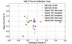
Figure 2. NMi Testing Mass Flow Accuracy vs. SMV results, 2-inch (50-milimeter) meter
NMi conducted further tests at Pigsar in Germany on natural gas at two pressures over a range of flow rates. Flow accuracy and verification results are presented for all of these tests for the 1-inch meter in Figure 1 and for the 2-inch meter in Figure 2. The flow accuracy of these meters is well within specification, and all of the verification results passed. Therefore, these are true positive results.
These figures show the mass flow accuracy on the Y axis and the meter verification results on the X axis. All of the process conditions are plotted on the graph. The mass flow accuracy is well within the corresponding accuracy specifications for liquid and gas. The direct stiffness verification results are well below the 4 percent specification limit. Indeed, under this range of process conditions the verification variation is ±0.30 percent.
These true positive results show that verification can confirm that a Coriolis flow meter is good, but it is important to also understand a verification technology’s detectability. Some examples of direct stiffness verification technology detecting failures follow.
True negative outcome
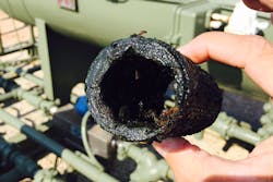
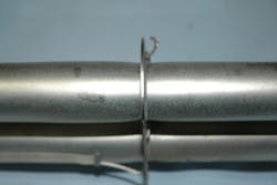
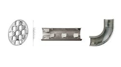
Image 2. Over-pressurized tube failure
The challenge with analyzing true negative results from Coriolis verifications is that relatively few field failures occur, so data is lacking. Of the hundreds of thousands of Coriolis meters actively in service by one Coriolis vendor, two failure cases have been identified and are presented below.
The first example in Image 2 shows a 2-inch, low-profile Coriolis meter used in an erosive slurry application. The calibration on this meter was suspect, and verification reported a reduction in stiffness outside the failure limit and flagged it as a failure. This meter was returned to the vendor for a quality inspection. Initial visual inspection showed clear erosion in the inlet manifold as shown.
This meter was flow tested using the as-found calibration values. The density was reading almost 0.25 gm/cm3 high with a mass flow error of more than 10 percent.
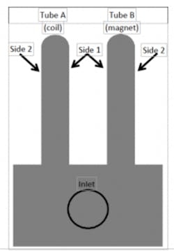
This meter was deconstructed, and wall thickness was measured on both tubes along the path length and around the circumference of the tubes as shown in Figure 3. Measurements show that one side of the inlet tube is eroded such that the thickness is reduced around 6 percent. Much of the meter appears to have experienced no thinning whatsoever.
Figure 3. Diagram of flow tubes showing location of wall thickness measurements.
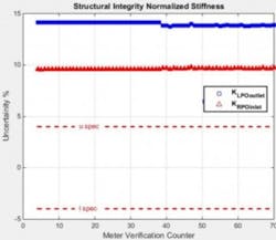
Figure 4 shows that the normalized stiffness for the inlet pickoff has decreased almost 10 percent while the outlet pickoff has decreased 8 percent, in line with the shift in the mass flow calibration factor. Other meter failures show that this is a coincidence — meter verification is not a meter factor technique. The meter had decreased in stiffness because of the wall reduction, resulting in over-stating mass flow. This decrease in stiffness reduces the drive frequency, causing the high density reading. All the data is consistent. The meter was un-repairable.
The second failed meter is another 2-inch meter of a different model type, a dual U-tube. This meter was built into a LACT skid, and the entire skid was hydro-tested during the factory acceptance test. The meter then failed the initial prove and was returned for quality inspection.
The quality team performed a meter verification and immediately suspected a problem. The stiffness had increased more than 10 percent. An as-found calibration was performed with the density reading almost 0.2 gm/cm3 low and a mass flow error of almost -4 percent (low). Just as the prior data was consistent with a decrease in stiffness, this data was consistent with an increase in stiffness. Experience with similar failures led the team to suspect that this meter had been over pressurized.
The case was removed from the meter, and immediately the over pressurization was obvious as shown in Image 2. The ballooning in the tubes around the brace bar shows that the tubes had well exceeded their yield point. This meter had been subjected to over 150 bar pressure, even though it only had Class 150 flanges. It was never resolved how this over pressurization happened. This meter was damaged beyond repair and scrapped.
Figure 4. Structural integrity normalized stiffness takes into account meter verfication counter and the percentage of uncertainty.
In the case of the eroded meter, the change in stiffness was well outside of specification before the meter was pulled out of service. If the user had established a work practice to routinely run meter verification and collect the results, the damage would have been detected and the meter pulled out of service much sooner. Frequent verifications are particularly important in processes where corrosion or erosion is expected.
For the over-pressurized meter, the user was not aware of meter verification. If verification results were available, the users would have simplified their troubleshooting and identified the problem more quickly. Presenting the verification results to the vendor would have streamlined the return and replacement process as well.
Both of these cases point out the need to have an -in-depth dialogue between users and vendors to understand the -process, the application and best way to incorporate verification -into -work practices.
True positive and true negative results are the diagonal terms of the hypothesis testing matrix. The next section discusses the off diagonal terms, false positives and false negatives.
False alarms and covert failures
Any verification technique has to balance the possibility of false alarms against the possibility of covert failures. Users do not want to spend what might be a lot of time and money stopping a process and troubleshooting a meter if it is really OK, but they do not want to leave a meter in service if it is truly inaccurate or dangerous.
The vendor should also provide information regarding how to react to a verification failure. For example, repeating the verification one or many times will show if the verification failure was caused by field effects or a real meter failure.
A very small percentage of users might be using Coriolis meters where they are expected to fail. For example, the Coriolis value proposition could be high enough that tolerating meter failure makes good business sense. For these users, verification can be very useful to manage measurement accuracy and safety, but covert failures in these applications need to be minimized. This small subset of users should have in-depth discussions with their vendors regarding meter verification technologies and how best to apply statistical methodologies to extract the most information for meter verification results.
Table 2. Entities that currently recognize/allow/accept verification in lieu of calibration or proving
Third-party recognition
Depending on the industry, users often cite the need for third-party agencies or regulator recognition of verification techniques to change work practices. Table 2 lists some of these entities that currently recognize/allow/accept verification in lieu of calibration or proving.
Meter verification techniques are evolving for flow meters in general. Magnetic, vortex and ultrasonic meter vendors all have active programs to add diagnostics to help verify meter accuracy and schedule maintenance. For Coriolis technology, users have expressed a strong need for tools where meter zero is examined and guidance is given regarding whether rezeroing is needed. Tools are available that perform a statistical evaluation of meter stability (flow and temperature) and help prevent the user from incorrectly rezeroing the meter.
Other strong needs include the ability to statistically trend the results of meter verification to provide advanced notice in the rare event of meter damage. This is particularly of value in known severe service, where the meter material of construction may not be fully compatible with the process fluid. Safety Instrumented Systems are another target application for statistical trending.
Upstream oil and gas customers, as well as those in industries where concentration is the primary variable, are very interested in being able to verify the Coriolis density and/or volume flow output. The enabling technology behind this would be coating detection. The challenge is discerning between a coating that shifts the density reading from a simple change in fluid density.
The perfect flow meter — zero calibrations, zero proving, no zeroing and zero worries with powerful diagnostics that can verify meter accuracy and give advance warning of changes — does not yet exist. Coriolis may arguably be the closest technology because it is largely insensitive to fluid properties. It is predicted that within 10 years, on-board meter verification diagnostics will be a standard expectation in Coriolis technology.
Verification will not replace proving or calibration, but it is already extending intervals. Proving and calibration are often regulated by legal and contractual arrangements. Verification is recognized by a growing number of agencies, and its techniques can provide an end-to-end check of the flow measurement system. Verifications look at a secondary set of variables to verify calibration; configuration, span and zero should all be verified. Span factor verification techniques vary — meter tube integrity is essential to meter verification.
Verifications are easier, cheaper and quicker than proving and can be performed remotely. They can be performed more frequently and generate statistical confidence. Verification can be applied in flow meter or process troubleshooting.
Tom O’Banion is the director of industry differentiation at Micro Motion Inc., a business unit of Emerson Process Management. He has more than 30 years of experience in the Coriolis market ranging from engineering, applications, and sales and marketing. He holds a bachelor’s degree in chemical engineering from the University of Colorado Boulder and an MBA in energy management from the University of Denver. He is a member of the Flow Control Editorial Advisory Board as well as Flow Research’s Calibration Working Group. He may be reached at [email protected].
