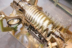
Axial compressors are typically used in applications with high flow rates and relatively low differential pressure (head) requirements. Contrary to centrifugal compressors, axial compressors do not change the direction of gas. It remains axial. The gas typically enters and exits the compressor in an axial direction parallel to the axis of rotation. First, the gas is accelerated, then it is diffused so its pressure is increased.
Axial compressors have relatively high peak efficiency. Their efficiency is good over a relatively narrow rotational speed range, but an axial compressor could achieve a higher efficiency under ideal conditions. Its complex and fragile structure combined with high starting power requirements are some of its drawbacks.
An axial compressor’s smaller diameter and sizes give it a lower frontal area and more compact design. Without these characteristics, an axial compressor would be mechanically less robust and much more aerodynamically sensitive to suction conditions and discharge pressure changes such as those induced by rapid throttle movements. All of these issues could lead to blade stalling and resulting surges, which could in turn produce catastrophic blade failures. In any axial compressor, the pressure increase per stage (each row of blades) is low compared to each centrifugal stage (impeller), requiring that at least two to four axial stages (rows with intermediate stator blades) be compared to each impeller in centrifugal compressors.
For some applications, a centrifugal compressor would be simpler and more reliable. Its ruggedness allows much more tolerance of the varying operating conditions and throttle changes encountered by a plant. Axial compressors should be used in large-flow applications where they can offer many advantages such as cost benefits and high efficiency. As a rough indication, such a large-flow service could be considered around and above 350,000 cubic meters per hour (m³/h).
Stall & surge
An axial compressor turns unstable when the flow rate decreases, the pressure ratio increases or sometimes when the aerodynamic load increases. Rotating stall and surge reduce performance drastically, so these instabilities should be properly respected in axial compressor design and operation.
Stalling, a kind of flow distortion, is an important phenomenon that affects the performance and reliability of an axial compressor. In simple terms, it is caused by the separation of gas flow at an axial compressor’s airfoil blades. Depending on the blade profile, this phenomenon leads to reduced compression and an efficiency drop.
Positive stalling flow separation usually occurs on the suction side of blades, while negative stalling flow separation occurs on the pressure side of blades. Negative stall could be negligible compared to the positive stall because flow separation is least likely to occur on the pressure side of a blade. In a multistage axial compressor, axial velocity is relatively small at high pressure stages. Stalling often starts near the hub and tip regions where size increases with decreasing flowrates. They grow larger at extremely low flow rates and affect the entire blade height. Delivery pressure significantly drops with large stalling which can lead to flow reversal. The stage efficiency drops with higher losses.
Nonuniformity of gas flow in the rotor blades may disturb local gas flow in an axial compressor without seriously upsetting it. The compressor may continue to work but with reduced compression capabilities. This is known as “rotating stall” that can reduce the effectiveness of an axial compressor; It can transfer to other more severe instabilities such as surge. The rotating stall can reduce an axial compressor’s efficiency and it could result in forced vibrations in the blades because of passage through the stall compartment. These forced vibrations may match with the natural frequency of the blades, causing resonance and blade failure.
Unstable flow in axial compressors caused by the complete breakdown of the steady flow is the surge. This phenomenon affects the compressor’s performance and is undesirable. It can result in serious damage of blades. In a compressor performance curve (pressure versus flow ), the line separating graph between the unstable and stable regions on the left side of the pressure-flow (head-capacity) plot is known as the surge line. This line is formed by joining surge points at compressor performance curves at different compressor speeds. The surge can cause vibrations in the whole machine and may lead to mechanical failure like blade failures. That is why the left portion of the curve from the surge point is called the unstable region, and that is why it may cause serious damage to the axial compressor. The recommended operation range is on the right side of the surge line with a proper margin.
Based on theoretical studies and thorough experiments, for any axial compressor system investigated an important nondimensional parameter exists on which the dynamic response depends. Whether this parameter is above or below a critical value determines which mode of compressor instability, rotating stall or surge will be encountered at the surge/stall line. For values above critical, the system will exhibit the large amplitude oscillatory behavior characteristic of surge, while for values below critical it will move toward operation in rotating stall at a reduced flow rate and pressure ratio. Theoretical results and the parameters could also be linked to the loading and flow coefficients, the tangential Mach number and the basic rotor geometry. In other words, by the reduction of flow rate in an axial compressor, the rotating stall might occur. Further flow rate reduction or a disturbance could transfer the rotating stall to a damaging surge.
Sophisticated flow systems & complex aerodynamics
The current trend in axial compressor design is to increase aerodynamic loads per stage and reduce the number of blades and stages. The pressure rise per stage and the efficiency should be increased, but the increased blade loading tends to decrease the stall margin and, therefore, can cause a reduction in the stable operating range of compressors. Many passive or active control devices are used to increase the efficiency and the stable operating range of axial compressors without any penalty on other performance parameters.
The aerodynamic stability of an axial compressor is usually limited by the behavior of tip leakage flows or the hub corner stall when the operating point gets closer to the stall or surge limit. In other words, performance improvements can be obtained using passive or active control devices that act on the behavior of tip leakage flows or the end wall corner stall, especially when the operating point gets closer to the stall or surge limits.
In simple terms, the casing treatment is the provision of sophisticated patterns of grooves (slots or similar) on the compressor casing designed to improve the aerodynamics of compressed gas in that area and surrounding zones as well as to improve the overall compressor performance and operation. One aspect of such provisions is the extension of the operating range using casing treatments, delaying stall or surge formation.
Casing treatments with slots (which might be axisymmetrical and nonaxisymmetrical), grooves, injection or recirculating of gases are important for axial compressors. These efficient approaches extend the stable operating range, especially by increasing the stall margin of an axial compressor system while the efficiency penalty should remain as small as possible. The hub corner stall can be controlled by aspirated systems and vortex generators. The casing treatment can induce additional losses at different operating ranges including peak efficiency condition. As a rough indication, using such a provision, stall margins could increase between 4 and 10 percent and the variation of efficiency might change about ±0.5 percent compared to a smooth casing configuration.
The casing treatment efficiency depends on the slot/groove location and details. For instance, grooves close to the trailing edge might be ineffective. The influence of the groove position, patterns and details have been studied by different experts. For example, a proposed configuration consists of five circumferential grooves. In this example, it was reported that for this configuration only the first groove had a beneficial effect at near-stall operating conditions and it increased stall margin, whereas the second one improved the pressure ratio and efficiency.
Another approach to control the flow near the rotor blade tip is based on the injection of high-momentum gas or a bleed of low momentum gas. The combination of injection and bleed leads to recirculating gas flow.
The compressor’s static pressure rise induces a recirculation of high-pressure flow from the rear to the front of a rotor. This can be achieved by either a single bridge, which creates a natural flow by two separate devices – one for the suction and another for the blowing. In many cases it was verified that the tip injection, if done properly, can increase stability. Some investigations reported an extension of compressor operating range up to 30 percent with sophisticated injection, bleed and recirculation systems.
The hub or casing corner stall is also a source of important losses and can be the cause of stall or surge. The injection and bleed techniques can be used to control this kind of flow. Beneficial effects of the boundary layer suction at the end wall and at the blade wall have been reported for different axial compressors. Another approach is based on the vortex generators. Their induced vortices mix high- and low-momentum flows near the wall, allowing the boundary layer to overcome a strong adverse pressure gradient. Such vortex generators have been applied to control the secondary flows, especially the hub or casing corner stall, to delay such stall.
Amin Almasi is a senior rotating machinery consultant in Australia. He is a chartered professional engineer of Engineers Australia and IMechE and holds bachelor’s and master’s degrees in mechanical engineering and RPEQ. He is an active member of Engineers Australia, IMechE, ASME and SPE and has authored more than 100 papers and articles dealing with rotating equipment, condition monitoring, offshore, subsea and reliability.
Amin Almasi
Amin Almasi is a lead mechanical engineer in Australia. He is a chartered professional engineer of Engineers Australia (MIEAust CPEng – Mechanical) and IMechE (CEng MIMechE) in addition to a M.Sc. and B.Sc. in mechanical engineering and RPEQ (Registered Professional Engineer in Queensland). He specializes in mechanical equipment and machineries including centrifugal, screw and reciprocating compressors, gas turbines, steam turbines, engines, pumps, condition monitoring, reliability, as well as fire protection, power generation, water treatment, material handling and others. Almasi is an active member of Engineers Australia, IMechE, ASME and SPE. He has authored more than 150 papers and articles dealing with rotating equipment, condition monitoring, fire protection, power generation, water treatment, material handling and reliability. He can be reached at [email protected].


