Part III: How Air Flow Affects Evaporative Cooling Tower Efficiency
By John Pitcher
This is Part III of a four-part series on the optimization of evaporative cooling towers. Parts I and II of this series appeared in the June (pages 20-23) and August (pages 18-19) issues of Flow Control.
Part II: How Changes in Flowrate Affect Evaporative Cooling Tower Efficiency
Part I: How Heat Loads Affect Evaporative Cooling Tower Efficiency
In the previous two parts of this series, we discussed the effects of heat load and water flow on evaporative cooling tower efficiency. Here we will consider the third and last variable, air flow. The study of the properties of air (although technically it can be any vapor with moisture content) is referred to as psychrometrics.
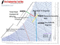
Figure 1. Psychrometric chart (Courtesy Engineering Toolbox)
A typical psychrometric chart is illustrated in Figure 1. Psychrometric charts are normally based on standard atmospheric pressure at sea level (29.92 inches of mercury) and represent 1 pound of air. As an example, let’s assume the temperature is 90 F and the relative humidity is 60 percent. Looking at the chart, the vertical blue line is the temperature line (also called the dry bulb temperature), and the yellow line following the curve is the relative humidity line. At the point where those two lines intersect, we can see the total heat content of the air is approximately 42 BTU/lbs. (green line), and what is called the wet bulb temperature (red line) is 77 F.
Other lines of interest are the specific volume line in orange, which runs diagonally; and the grains of moisture line in purple, which runs horizontally. The specific volume at the point where the red, yellow and blue lines intersect would be about halfway between the 14 and 14.5 lines, or about 14.25 cubic foot per pound. This tells us that 1 pound of air will occupy 14.25 cubic feet of space. Specific volume is the inverse of density or, in English, 1specific volume = density. So if the specific volume is 14.25, the density of the air is around 1 14.25, or .07 Lbs. per cubic foot. At 90 F and 60 percent relative humidity, one cubic foot of air weighs 0.07 pounds. Knowing specific volume or density becomes important when performing fan calculations. For example, if a fan is delivering 100 CFM of air at 90 F and 60 percent relative humidity, how many pounds of air are being moved every hour?
The formula is CFM X density = pounds of air per minute (Lbs. per Min) or CFMSpecific Volume = Lbs. per Min. So, 100 X .0172 = 7.2 or 100 ÷ 14.25 = 7.2. Therefore, the fan is moving around 7.2 pounds of air per minute. By multiplying Lbs. per Min times 60 minutes per hour, the result is 7.2 X 60 = 432 pounds of air moved per hour.
Following the grains of moisture line horizontally to the right from our spot reveals that the total amount of moisture in weight would be around 139 grains. Grains are a measurement of weight as 7,000 grains is equal to 1 pound. Therefore the water vapor in 1 pound of air at 90 F (dry bulb) and 60 percent relative humidity would have a weight of (139 7,000) around .0199 pounds.
The light blue line in Figure 1 represents the dew point temperature. Dew point is the temperature at which the water vapor in the air will change back to a liquid. This tells us that at 90 F and 60 percent relative humidity, droplets will form on the surface of your adult beverage container (or any other surface) if it is below 73 F. Dew point becomes useful in dehumidification processes, as a coil at or below this temperature will remove moisture from the air.
Wet-Bulb’s Role In Evaporative Cooling Tower Applications?
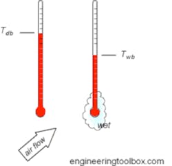
One of the most important factors in understanding evaporative cooling towers is wet bulb. Wet bulb is simply a temperature measured by taking a regular thermometer and placing a cotton sock or wick at the bulb, which is saturated with distilled water, and placing it in air moving at some velocity as shown in Figure 5. When compared to a thermometer without a sock, also called a dry bulb thermometer, it is possible to calculate relative humidity. For example, at 100 relative humidity, both the dry and wet thermometers will be the same temperature, as the air already holds all the moisture it can. As the relative humidity falls, the temperature of the thermometer with a sock (wet bulb) will drop due to evaporation and become less than the dry bulb thermometer. The greater the difference, the lower the relative humidity.
Figure 2. Wet and dry bulb thermometers (Courtesy Engineering Toolbox)
Wet bulb temperature is important to understand because the temperature of the water leaving an evaporative cooling tower is determined by, and directly related to, whatever the outdoor air wet bulb temperature is. Furthermore, the water leaving the tower can be the same but never lower than wet bulb temperature.
Heat Exchangers for Evaporative Cooling Tower Applications
Heat exchangers of various types, shapes and sizes are used extensively in industry. One thing that most have in common is that they are devices designed to transfer heat as efficiently as possible between two different fluid streams. Evaporative cooling towers are no exception, as they transfer heat from a process load using water to the air flowing through the tower to the atmosphere.
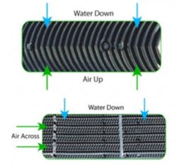
Evaporative cooling towers can be designed to operate as either a cross flow or counter flow.
Figure 3. Counter flow and cross flow heat exchange (Courtesy Baltimore Aircoil)
As shown in Figure 3, the heat exchanger to the top is a counter flow type. This is because the fluid streams move in opposite directions. To accomplish efficient heat transfer, the cooler fluid in one stream begins by contacting the warmer stream of the other. The figure on the bottom is a cross-flow type. In a cross-flow application one stream moves parallel of the other.
A very important factor to consider with heat exchangers is concept of approach. Approach is calculated by knowing the difference in temperature between the inlet of one stream and the outlet of the other. For example, a refrigeration system uses an evaporative cooling tower to remove heat from the refrigerant at 105 F via a heat exchanger called a condenser. When the outdoor conditions and the load on the refrigeration system are at their maximum, the tower water temperature leaving the heat exchanger (condenser) is designed to be 95 F, therefore the design approach would be 105 – 95 = 10 F.
In evaporative cooling towers, the approach is the difference in temperature between the water leaving the tower to the process and the wet bulb temperature of the air entering the tower. If the design temperature of the water leaving the tower is 85 F, and the design wet bulb temperature entering the tower is 78 F, the design approach is (85 – 78) = 7 F.
Probably the three most important design criteria for specifying evaporative cooling towers are the maximum design water temperature the process requires for cooling, the range between the water entering and leaving the tower, and the maximum wet bulb of the air entering the tower. For example, if the climate where a tower is placed has a maximum outdoor wet bulb temperature of 77 F, and the maximum temperature supply water that the process can tolerate is 85 F, and the temperature of the water entering the tower is 95 F, then the design approach would be the difference between the maximum tolerable process supply water and the maximum design wet bulb (85 – 77) = 8 F, and the range would be (95 – 85) 10 F. In this application, the maximum design tower approach would be 8 F. This means that a tower with an approach higher than 8 F would be undersized and not able to provide cool enough water to the application when outdoor temperatures and heat load are at maximum.
Specifying towers with a lower than maximum design approach can be more energy efficient; however, this efficiency comes with higher upfront cost. This means that it is possible to have two towers rated for exactly the same amount of heat removal and range, but if they have different approaches they will not be the same size or cost. Further, as the approach reaches closer to zero, the size and first cost of the tower go up exponentially.
Psyching Out the Evaporative Cooling Tower
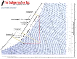
Two different scenarios are shown in figures 4 and 5 — one showing the air dry bulb entering the tower is lower than the process water; and the other showing the air dry-bulb entering the tower is higher than the process water.
Figure 4 represents a condition where the process water temperature is greater than the outdoor air. The triangle drawn on the chart shows the heat flow using yellow lines. Let’s assume that the process water temperature entering the tower is 80 F, and the air entering the tower is 55 F with a relative humidity of 70 percent. The amount of heat the air contains entering the tower is roughly 20 BTU/lbs., as shown by the yellow line at the bottom of the triangle. As the air comes in contact with the 80 F water in the tower, due to the fact that it is at a lower temperature, it will rise in temperature until it finally reaches the temperature of the water (80 F). The air‘s heat content becomes around 26.5 BTU/lbs., as illustrated by the yellow line coming from the base of the triangle. This tells us that it takes about (26.5 – 20) about 6.5 BTU/lbs.. for the air to change temperature from 55 F to 80 F. As the water evaporates it gives up both moisture and heat to the air until the air holds all the moisture it can and reaches 100 percent relative humidity. This is represented by the yellow line at the top of the triangle.
So now the air that started out as 55 F and 70 percent relative humidity becomes 80 F at approximately 100 percent relative humidity and holds around 43.4 BTU/lbs. of heat. The amount of heat gained by the water evaporating and giving up heat is about (43.4 – 26.5) or 16.9 BTU/lbs. The total heat taken from the tower is roughly (43.4 – 20) or 23.4 BTU/lbs. So, the amount of heat to change from 55 F to 80 F was 6.5 Btu/lbs., and the amount of heat to change from 70 percent relative humidity to 100 percent relative humidity was 16.9 Btu/lbs.
This may initially sound a little counterintuitive, but the dry bulb temperature means very little in this equation. This is the reason why the BTU/lbs. line is merely an extension of the wet-bulb line (only farther left). As such, the total heat that is removed is completely dependent on the wet bulb What do I mean by that? At 55 F and 80 percent relative humidity, the wet bulb is around 50 F. If the dry bulb were to reach 65 F at a 30 percent relative humidity, the wet bulb would still be around 50 F and the amount of heat given up to the water would still be the same amount (roughly 23.4 BTU/lbs.). The only difference is that the amount of sensible heat would decrease to roughly 5 BTU/lbs., while the latent heat would increase to 18.4 BTU/lbs.
Figure 4. Water temperature lower than dry bulb (Courtesy Engineering Toolbox)
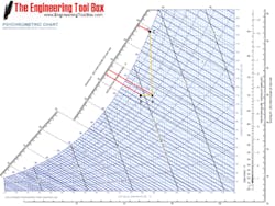
On the other hand, what would happen if the water temperature was less than the air dry bulb entering the tower, as shown in Figure 5? Let’s assume the water temperature is 80 F and the air temperature entering the tower is 85 F with a 60 percent relative humidity. At point "A" in Figure 5, the air contains about 38 BTU/lbs. of heat. Because the air is at a higher temperature than the water, it gives up heat to the water, shown at point "B." Now the air contains a total heat of around 37 BTU/lbs. This means the total amount of heat given up by the air into the water is around 1 BTU/lbs. From point "B," the air becomes the same temperature as the water at 80 F dry bulb, and the relative humidity changes to around 70 percent. This decrease in relative humidity is not because moisture was added, but rather because the air at a higher temperature simply has a greater ability to hold moisture. Remember, relative humidity is dependent on temperature, and as temperature goes up, air can hold more moisture. From point "B," the water begins to absorb moisture through evaporation until it reaches a relative humidity of around 100 percent at point "C" where the BTU/Lbs. of the air becomes about 49.2 BTU/lbs. and gains a total of 49.2 – 38 = 11.2 BTU/lbs.
Figure 5. Water temperature higher than dry bulb (Courtesy Engineering Toolbox)
What Have We Learned Grasshopper?
The air that is entering the tower fan at the top of the tower is at 85 F and 100 percent relative humidity. It is also the point where the air enters the fan so the fan is taking in the air at this condition. If you line up that point on the chart and estimate what the specific volume is, Figure 5 shows the diagonal direction of the specific volume lines, you should come up with a number around 14.4 cubic feet per pound (between the 14 and 14.5 lines).
If you recall when we discussed specific volume, we gave an example of how many pounds of air per hour a 100 CFM fan would be moving. Using this same example of 100 CFM, how many pounds per minute would we be moving per minute?
CFM dived by specific volume = 100 ÷ 14.4 = 6.95 pounds per minute
or
CFM times density = 100 X (1specific volume) = 100 X 0.069 – 6.95 pounds per minute
Great, so now tell me how much heat per hour is being removed based on Figure 5?
The formula is total heat removed (11.2) times pounds per minute of air (6.95) times 60 minutes per hour.
Heat Removed times Lbs./Min times 60 (converting minutes to hours) or
11.2 X 6.95 X 60 = 4, 670.4 BTU/Hr.
Therefore, a tower with a 100 CFM motor at these conditions would be removing 4,670.4 BTU/Hr.
For extra credit, how many CFM would we need to make a full cooling tower ton at this condition?
Well let’s see … a cooling tower ton is 15,000 BTU/Hr. By reversing the procedure we first solve for how many pounds of air we need. So the amount of heat removed from 1 pound is (49.2 – 38) = 11.2 BTU. Therefore, it will take 15,000 divided by 11.2 around (15,000 ÷ 11.2) = 1,340 pounds of air per hour. Dividing that by 60 minutes per hour gives us 1,340 60 = 22.33 pounds of air per minute. Now we have to convert pounds of air per minute into cubic feet of air per minute so:
Pounds of air per minute (22.33) X specific volume (14.4) = roughly 322 CFM/Ton
or
Pounds of air per minute (22.33) ÷ density (.069) = roughly 322 CFM/Ton
The full equation then is:
CFM/Tower Ton = (15,000 X Sp. Volume) ÷ ([Ht. 2 – Ht.1] X 60) = 322
or
CFM/Tower Ton = 15,000 ÷ ([Ht.2 – Ht.1] X 60 X density) = 322 CFM
So a fan would need to produce 322 CFM to produce a tower ton of cooling at these outdoor conditions.
Last question, what size cooling tower would we need for the 350,000 ÷ BTU/Hr. oven in our previous example? Tons = 350,00015,000 = 23.33 Tons. If the air was at the above conditions we would need 322 X 15 = 4,830 CFM.
John Pitcher is the CEO of Weber Sensors, a 50-year-old German manufacturer of flow products based on the calorimetric principle of operation. Previously he was the founder of Scientific Conservation, which was one of the first companies to use cloud computing for fault detection and diagnostics. Mr. Pitcher’s 40-year career covers many product development and leadership roles in the automation and energy efficiency fields. He can be reached at 770 592-6630 or [email protected].
