As all segments of the building industry move toward the 2030 goal of net zero energy buildings (NZEBs) — buildings that produce as much renewable energy as they consume on an annual basis — heating, ventilation and air conditioning (HVAC) system design is at the forefront of these efforts.
In a report by the American Society of Heating, Refrigerating and Air-Conditioning Engineers (ASHRAE), ASHRAE Vision 2020, Producing Net Zero Energy Buildings, the standards-setting organization acknowledges, "If NZEBs are to become reality … designers will need the tools to design and apply better integrated equipment, manufacturers will need to produce ultra-high-efficiency equipment and know how to best apply it to buildings."
Since ASHRAE issued this report in 2008, progress has been made on many fronts toward improving efficiency and reducing energy consumption, most notably the issuance in 2015 of the U.S. Department of Energy regulation that set minimum efficiency standards for clean water pumps. When the Energy Conservation Standards for Pumps takes effect in 2020, only pumps that meet the pump efficiency index rating will be allowed in commerce in the U.S. (The rule does not affect pumps already installed, though operators can improve system efficiency by replacing older pumps with newer models.)
Modern pump designs incorporate cutting-edge computational fluid dynamics technology to maintain significantly higher levels of efficiency over a much wider range of operating conditions. Using high-efficiency pumps with properly applied variable speed controls will warrant significant energy savings for a given hydronics system.
New tools for the industry
An HVAC system made up of the highest-efficiency components will only enjoy the efficiency gains of these components if it is designed, installed and operated as a system. In its visioning report, ASHRAE points to the importance of the early stages of system design: "Architects, engineers and manufacturing companies will need refined tools for properly sizing and selecting HVAC equipment in net zero buildings."
While many manufacturers offer online specification of pumps for HVAC systems to help achieve goals related to energy consumption, efficiency and system costs, designers typically do not apply load profiles to pumps as part of their selection processes, resulting in systems that are not fully optimized for efficiency.
General industry practice has been to make pump selections based on a system’s design load or the maximum capacity, even though centrifugal pumps installed in HVAC systems operate at part-load conditions a majority of the time. Flow requirements fluctuate constantly throughout the year based on the heating or cooling load of a building at any given time. However, with the traditional pump selection approach, pumps were selected at 100 percent load conditions, even though the system generally only operates at that level for 1 percent of its yearly operation. Actual efficiency depends on the configuration of the pump versus load and flow conditions.
Figure 1. Typical closed-loop HVAC system. Constant head differential must be maintained at all times.
By applying a new specification formula that accounts for variations in load profile, HVAC designers now have the tools to select pumps based on real-world system demands to ensure the most efficient system performance.
Part Load Efficiency Value (PLEV) is a calculation that accounts for the entire variation profile and flow requirements based on the actual heating or cooling load in a commercial building’s HVAC system, not just the best efficiency point (BEP).
PLEV is derived from the successful Integrated Part Load Value (IPLV) performance calculation developed by the Air- Conditioning and Refrigeration Institute (AHRI) in AHRI 550/590-1998. The proven formula describes the equipment efficiency while operating at various capacities of a chiller system and is crucial in supporting energy use and operating costs throughout the lifetime of the system. Because of its wide acceptance by chiller manufactures as a baseline comparison between manufacturers, similar correlations can be adopted for centrifugal pumps used in heating and cooling systems.
Real-world assessment
The PLEV equation is as follows:
A, B, C and D are the pump efficiency values at 100 percent, 75 percent, 50 percent and 25 percent of the flow rate and at the corresponding head value on the control curve. Based on the equation, during any given year the pump will operate at 100 percent flow (duty point) only 1 percent of the year, 75 percent flow 42 percent of the year, 50 percent flow 45 percent of the year and 25 percent flow 12 percent of the year.
The subscript "v" denotes variable speed operation with the control, or fixed head, calculated within a system’s critical circuit. Selection software that includes the PLEV calculation defaults to 30 percent of pump’s total design head (TDH) to represent the minimum control head within a system. ASHRAE 90.1-2013 guideline requires that the total head loss in a system be calculated, making it natural to calculate the critical zone’s fixed head, too. This is the number that should be used because it represents a more accurate calculation, which will be reflected in the cost analysis.
Figure 2. Typical closed-loop HVAC system. Constant head of 17 feet total dynamic head
Most heating and cooling systems are closed-loop and require a constant head differential at all times. The constant head differential is necessary for system control and to ensure that the necessary differential head across any controlled subcircuit is maintained during operation.
PLEV can be used to accurately compare pumps from different manufacturers to identify overall operational efficiency. The 30 percent of TDH, or calculated minimum control head within the equipment schedule along with specifications, will ensure a fair, apples-to-apples comparison among manufacturers.
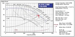
PLEV provides system designers more latitude in selecting pumps slightly to the right of the BEP, if a detailed system head loss is calculated. Pump selections to the right of the BEP may have a higher PLEV than other selections because the PLEV load profile is heavily weighted at part-load conditions, mainly 75 percent and 50 percent operation.
Figure 3. Example of a higher PLEV pump selection to the right of BEP at full load
These load profile points alone make up 87 percent of the operating hours. Designers must be aware that even though most of the building’s operation is 87 percent part load, pumps still need to operate at the 100 percent full-load condition.
ASHRAE guidelines prefer pump selections between 85 and 105 percent of BEP as well as selecting pumps to the left of BEP. If system head loss has been estimated and a selection is made to the right of BEP, the pump could run outside the acceptable range of operation. In a worst-case scenario, the pump may run off the end of the pump curve. As noted above, pump selections to the right of BEP should only be made if a detailed head loss calculation has been completed.
PLEV selection criteria itself does not provide energy savings in an HVAC system. Rather, it is a tool to help designers select pumps that operate at the highest efficiencies across a building’s operating conditions.
When combining highly efficient pumps with the PLEV selection criteria, system designers can maximize operational performance while realizing energy, cost savings and environmental benefits. Ambitious goals for net zero energy buildings along with more stringent pump efficiency standards spur system designers to seek smarter ways to specify pumps. The PLEV selection criteria and selection software offer tools to meet and exceed efficiency requirements.
Mark Handzel is vice president, product regulatory affairs, and director, HVAC commercial buildings, at Bell & Gossett, a Xylem brand. He is a member of the Appliance Standards and Rulemaking Federal Advisory Committee’s Commercial and Industrial Pumps Working Group.


