Calibration Corner: Steps for troubleshooting control signals
Finding a balance between keeping control systems running at peak efficiency without spending exorbitant amounts of time doing so is the goal of every instrument and automation technician. The constant challenge is to keep the instrument loops and input/output (I/O) signals highly accurate, and doing it as quickly as possible.
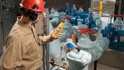
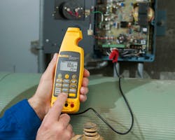
One of the easiest ways technicians have been able to save time when troubleshooting issues involving control signals is by measuring loop current without breaking the circuit by using a mA clamp meter. Pairing this tool with the functions of a loop calibrator allow technicians to troubleshoot with more advanced tools.
Monitoring control signal problems
Keeping an eye on a handful of areas across your facility can highlight issues with the control loop early on. The first indication of issues often comes from an operator noticing a bad valve or components not responding the way they used to. No matter how the issue is brought up, it then falls on the technician to begin troubleshooting. With hundreds, or even thousands, of control loops networked together throughout a processing plant, you have to figure out where and what the issue is before you can mitigate it.
Troubleshooting a dead loop causing control signal problems
If you are looking at a dead loop, check the wiring, power supply, transmitter and final control element for problems. As you take each measurement, you will be able to isolate the issue.
Wiring
The first step is to measure the 4-20 mA signal. Using a mA process clamp meter, you can make this measurement without breaking the loop, saving quite a bit of time. If you are using a digital multimeter, you will need to break the loop connecting in series to verify the loop current value. If the current measurement raises a red flag, you are likely looking at one of three causes:
- Shorted/broken/disconnected wires
- Bad power supply
- Faulty instrumentation
Power supply
If you get no 4-20 mA loop measurement, the next measurement to take is on the loop power supply. This measurement can be made with a digital multimeter or a process mA clamp meter. If the power supply shows no output, use the loop power function on your meter to provide a source — if the loop then works as it should, you have discovered the problem.
Transmitter
If the problem is not with the wiring or the power supply, the transmitter is next on the list to check. Using the mA simulate mode on a loop calibrator, process calibrator or multifunction clamp meter, test to see if the loop functions as you would expect. If it performs properly with the calibrator or meter as the source, the issue is with the transmitter itself. Or, if it is a new installation, it could be miswiring or the sensor’s input to the transmitter.
If the system does not perform properly with the meter as its source, there is one more area to check.
Final control element
The last area to take a look at is the final control element. If an element like the valve positioner is suspected, you will want to use the mA source and simulate mode on the mA process calibrator to feed a signal to it. Depending on the response you see from the local indicator, you may have uncovered the issue in the control signal.
Troubleshooting an inaccurate loop causing control signal problems
If the problem you are seeing is not a dead loop, but an inaccurate one, you are looking at possible issues including a bad I/O card or a bad final control element. Looking into this kind of issue, you will want to start by looking at the final control element and then the I/O card.
Final control element
Use a clamp meter to measure current on the loop. Compare that measurement to the local position indicator on the valve. Take those measurements to the operator to verify findings.
PLC and DCS I/O card
If you are looking at a measurement loop, take the same measurement: loop current with a clamp meter. But this time, check in with the operator to see how well the measured value at the control panel agrees with the actual loop current. This can give you a quick read on the input/output (I/O) cards on programmable logic controllers (PLCs) and distributed process control systems (DCSs).
The mA process clamp meter can be used as an accurate signal source to check their operation. When measuring a 4-20 mA input card, you will need to disconnect the process loop and use the meter’s mA source function to be the known source value and compare that to the value shown at the operator’s readout. For voltage input cards, the process is the same except for using the voltage source function instead of mA source.
Logging measurements
If neither of these measurements are showing where the issue is coming from, it could be from a random fluctuation or intermittent fault. This requires a more advanced tool setup to measure — you will want to use a clamp meter with a scaled mA output and then feed that output into a logging multimeter or a power quality logger to record current measurements over time. This mode on the clamp meter will measure current in the loop without breaking the circuit and also produce an identical and isolated mA output. The logging feature it is fed into will capture any disturbances.
Field checks
Even periodic in-field tests need to be done for preventive maintenance programs, and the ability to check each loop for current in a matter of sections, without needing to disconnect anything, saves time. A process mA clamp meter can handle most of the necessary functions and can even be used in the field to quickly check electronic valve positioners, mechanical position indicators or flow indicators as input changes are made.
Monitoring control signal problems with one tool
Most loop calibrating and troubleshooting can be done with one tool instead of a number of separate instruments: a process mA clamp meter. When you are looking for issues with control signals, start by checking each loop for current without disconnecting anything. If current is not present on some loops, check the wiring, power supply, transmitter and final element. Also check the control system’s I/O cards by using the clamp meter as a known signal source while in contact with the operator to verify what you are both seeing. That could mean there is an issue with the transmitter itself, or the installation of the transmitter.
Bob Crepps is a product specialist with Fluke Corporation, focusing on the process calibration tools group. He has more than 30 years of experience providing technical support and training in the electronics industry. Crepps has been offering his expertise to Fluke Process Tools for 10 years.
About the Author

Bob Crepps
Product specialist with Fluke Corporation
Bob Crepps is a product specialist with Fluke Corporation focusing on the process calibration tools group. With more than 30 years of experience providing technical support and training in the electronics industry, Crepps has been offering his expertise to Fluke Process Tools for 10 years.

