Calibration Corner: Control testing without breaking the loop
In many processing plants, taking downtime to troubleshoot controls is simply not an option. But these plants still need to troubleshoot control for temperature, pressure, flow and pH devices and valves. The thing all of these control devices and valves have in common is that they are often all fed into a 4 to 20 mA signal. The simplicity of the 4 to 20 mA loop’s design masks just how difficult the challenge of keeping a plant running optimally is when tackling this task with conventional electronic measurement tools.
Measuring in the loop
For food and beverage manufacturing, measuring current by making a connection within the circuit under test, which often requires powering down the circuit and breaking the loop, is not a viable alternative. Following this process, a mA calibrator or digital multimeter would be used to measure the 4 to 20 mA loop, meaning shutting down the power to multiple systems to make the necessary measurements.
In the past, the only way to troubleshoot these instruments — like those used with boilers — was when they were shut down. That meant waiting for planned outages with long waiting periods in between when you could not verify that a process control instrument was actually working as expected unless you had a tool like a milliamp process clamp meter.
Instead, taking measurements while instruments are still powered up and running is the best option available. It cuts down on waiting time, and uncertainty in between measurements.
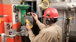
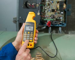
Doing this with a mA clamp meter allows for measurements to be made without disrupting the circuit. Specifically designed milliamp process clamp meters allow for 4 to 20 mA loop measurements to be made and calibrations performed with no interruption to the circuit or power within the plant.
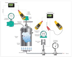
With a mA clamp meter, you can measure the circuit loop between the instrument and the distributed control system (DCS), paying additional attention to the percentage readings, without needing to disconnect a thing. As shown in the figure above, loop measurements can be taken anywhere on the boiler, 4 to 20 mA loop circuits to ensure the process is working smoothly, or to raise any issues before they become too large and cause additional damage.
Why use a 4-20 mA loop?
The 4-20 mA current loop is commonly used in processing facilities all over the world to transmit sensor information. It allows process monitoring, typically in systems monitoring temperature, pressure, flow and pH. The usual setup for these systems is the 2-wire, 4 to 20 mA current loop. This has a single twisted-pair cable that supplies power to an instrument while also carrying the 4 to 20 mA signal.
The current loop is particularly useful in transmitting sensor information when the signal has to travel long distances — this is not an uncommon need in large facilities, often 1,000 feet or more. The setup using a basic two-wire technology makes installing the loop both inexpensive and simple to wire, maintain, troubleshoot and repair if any issues occur.
The operation is pretty straightforward, which is part of the simple beauty of a 4 to 20 mA loop. A sensor’s output signal is converted to proportional current, with 4 mA usually representing the sensor’s zero-level output, and 20 mA representing the sensor’s full-scale output. For example: a reading of 20 mA means that the valve is 100% open, running at full-scale. A reading of 4 mA means that it is closed, or at 0%. Readings between these values show how much the circuit is controlling the valve, with the percentage showing how open, or closed, the valve is.
At this point, you are probably asking “why is 4 mA zero instead of 0 mA?” The answer to that is because the design allows room to show there is a fault caused by an open circuit or a lost feed. The reading of 0 mA is essentially reserved to show there is a fault in the system, showing a negative percentage to also heighten the warning bells. So, a reading between 4 mA and 20 mA indicates a properly working circuit.
One of the key advantages of using a 4 to 20 mA current loop is that the accuracy of the signal is not affected by a voltage drop in any interconnecting wiring. The loop can supply operating power to the device in these cases. Even if there is a significant amount of electrical resistance on the line, the current loop transmitter can still maintain the proper current, up to its maximum voltage capability.
Some mA clamp meters offer a percentage span feature that displays the span for 4 to 20 mA loops. This percentage reading gives the technician another way to track critical indicators by showing percentage flow at the central DCS level, based on the milliamp measured.
Certain mA clamp meters will not only display the measurement, but also the percentage span, as mentioned earlier. These clamp meters can help further simplify measurements on a 4 to 20 mA loop. Showing the percentage clues a technician in to how much the valve is open as well as any issues that could be present.
Troubleshooting control loop problems
Since the 4 to 20 mA loop is the clear winner for running temperature, pressure, flow and pH values through a facility, being able to ensure accuracy and troubleshoot when an issue does occur is paramount, especially in the food and beverage manufacturing environment.
These measurements are needed to verify continued compliance with EPA-mandated requirements and safe, proper use of the boilers within the facility. However, the information often routed to a DCS is not available for troubleshooting or calibration while the boiler is in operation. With all of these systems and control meters interconnected, you cannot just go in and disconnect one piece to measure or calibrate it — not only is it costly, but it could trip other assets down the line and cause damage.
Because a mA clamp meter can be used to measure current on these assets without having to power anything down, a facility can be confident in their instruments and their compliance to regulations. This not only allows a facility to keep running smoothly, but it also allows for preventative maintenance to be done regularly. Including a mA clamp meter in your preventative maintenance route means you can find faulty valves or catch issues before they get too big.
Bob Crepps is a product specialist with Fluke Corporation, focusing on the process calibration tools group. He has more than 30 years of experience providing technical support and training in the electronics industry. Crepps has been offering his expertise to Fluke Process Tools for 10 years.
About the Author

Bob Crepps
Product specialist with Fluke Corporation
Bob Crepps is a product specialist with Fluke Corporation focusing on the process calibration tools group. With more than 30 years of experience providing technical support and training in the electronics industry, Crepps has been offering his expertise to Fluke Process Tools for 10 years.


