PUMP GUY MAILBAG: Minimum Acceptable Flow for Effective Pump Operation
(a.k.a. "The Pump Guy")
Larry,
Please enlighten me. For a constant speed centrifugal process pump, what is the minimum stable acceptable flow for safe operation?
K. Stone
M.E.
###
Hello K. Stone,
There are a few answers to this question. All are valid, depending on the answer you seek. The teacher asks the little kindergarten student, “Where does milk come from?” The child answers, “The refrigerator.”
Is the child wrong? Is that what the teacher wanted to know?
Maybe a process pump has a best efficiency flow of 800 GPM. If the process engineer tells the equipment operator to throttle a control valve and hold the pump between 85 percent and 110 percent of best efficiency flow, then the answer is 680 GPM minimum on the flowmeter. Does this answer your question?
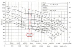
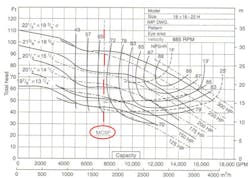
A performance curve accompanies all industrial pumps. The pump factory normally provides the performance curve based on water at 70 F and corrected to sea level. Some factory performance curves will indicate the minimum continuous stable flow (MCSF) on the curve. Is this what you wanted to know?
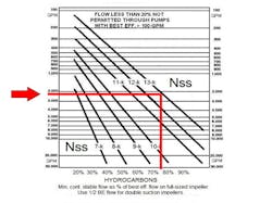
Another indicator of the pump’s minimum stable flow is in a design parameter called the suction-specific speed. The suction-specific speed uses information from the pump curve, applied to a simple mathematical manipulation and a graph that indicates the minimum flow as a percentage of best efficiency flow.
You can obtain the graph from various sources, including your pump supplier and most books on pumps. I first saw the graph in a pump book published over 60-years ago. I found the book gathering dust on a shelf at a used book store. I paid two bucks for it.
READ ALSO: Why You Need to Know About Suction-Specific Speed
A Few Thoughts on the Suction Specific Speed
Last week I installed a high-efficiency water heater in my home. The sale price was 40 percent more than the cost of a comparable standard water heater. My high-efficiency heater consumes over 1,000-kW/year less than my previous water heater.
The cost of energy and fuel is rising. We all know we should drive economical cars, but the commercials on TV tell us we should buy cars with explosive acceleration. You can have explosive acceleration or fuel economy, but not both in the same vehicle. The two features are mutually exclusive.
Mutually Exclusive Features
Pump engineers and users also want two mutually exclusive features in a process pump. We want the ability to operate a process pump efficiently all over the performance curve. At the same time, we want a pump that requires low suction energy, called NPSHr.
Pump designers can give us impellers designed with a broad window of good efficiency. Or, they can give us a pump impeller that requires low suction energy (NPSHr). But they can’t give us both in one impeller.
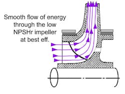
When operated at best efficiency coordinates, the impeller with a broad performance window exhibits an uninterrupted and undisturbed flow pattern of energy through the impeller. With restricted flow, the performance impeller exhibits mostly the same undisturbed flow pattern of energy through the impeller.
Likewise, a process pump with a low suction energy impeller operated at best efficiency exhibits a similar smooth flow pattern of energy through the blades.
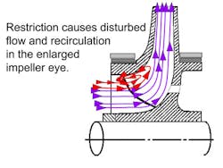
However, any restriction that drags the low NPSH impeller to the left of best efficiency causes a disturbed flow through the impeller blades.
This is similar to a traffic jam on the highway when four lanes of cars try to squeeze onto a two-lane road. The liquid is forced to re-circulate in the enlarged eye of the low NPSH impeller and produces the cavitation-type phenomena known as internal re-circulation. Internal re-circulation makes the noise of cavitation and leaves its signature damage on the impeller blades when the pump operates to the left of best efficiency.
To avoid this problem, and the resultant pump damage and maintenance, these low NPSH pumps must be operated within a controlled (reduced) operating window. In short, these pumps must be operated close to best efficiency.
This operating window is quantified or rated by the term “Suction Specific Speed” (SSS). The SSS is calculated with three parameters available on the pump’s performance curve. Get your pump curve, and find the pump speed in RPM. Find the flow at best efficiency on the full-sized (uncut) impeller. For double-suction impellers, use half BEP flow. Find the NPSHr at best efficiency.
The formula is:
The SSS relates the speed, flow and NPSHr into an operating window that can be expected from a pump. It is a valuable tool for the process engineer, and for the operators interested in keeping the pump running without problems.
The SSS is an indication of the pump’s ability to operate away from its design point—called the BEP—without damaging the pump.Here is an example:Let’s say you are pumping kerosene with an end suction (OH) API one-stage centrifugal pump. The pump/motor speed is 3,500 RPM. Best efficiency flow is 2,250 GPM. NPSHr is 30’ at best efficiency.
Therefore the SSS is 12,960. Plot a line from 2,250 GPM to 12,960 on the graph, and plot a line down to the bottom of the graph.
This pump should not be operated at less than 78 percent of best efficiency flow. Seventy-eight percent of 2,250 GPM is 1,755 GPM. If the operator throttles this pump to 1,600 GPM and goes to lunch, he’ll probably have an emergency pump failure when he returns from lunch break.
This failure would be a design-induced failure, or an operations-induced failure. If you mistreat your car, you cannot blame the mechanic. A low-flow sensor could block this or sound an alarm.
Someone should teach the pump operators to always maintain flow above 1,900 GPM (safety margin) on this pump if there is interest in improving the reliability.
The operating window is the effective zone around the BEP on the pump curve that must be respected by the process engineer and/or the operators of the pump. If not, these pumps will vibrate, cavitate, overheat, distort, wear, bind, gouge, and suffer premature seal and bearing failure.
How far away from best efficiency a pump can operate on its performance curve without damage is determined by its impeller’s suction specific speed.
I urge everyone who works with process pumps to locate and use their pump curves, which can typically be downloaded from the pump manufaturer’s website.
Regards,
The Pump Guy
These issues and others are covered during Larry Bachus's Pump Guy Seminar program. For more information on upcoming Pump Guy Seminar trainings, visit flowcontrolnetwork.com/pumpguy.
Larry Bachus, founder of pump services firm Bachus Company Inc., is a regular contributor to Flow Control magazine. He is a pump consultant, lecturer, and inventor based in Nashville, Tenn. Mr. Bachus is a retired member of ASME and lectures in both English and Spanish. He can be reached at [email protected].
