Coriolis Flow Measurement – Past, Present & Future
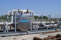
Rheonik, the first supplier to offer Coriolis flowmeters for larger line sizes, recently divested from GE Measurement & Control and is once again an independent company, operating under the name Rheonik Messtechnik GmbH. (Photo courtesy Rheonik).
Coriolis flowmeters were first brought onto the market by Micro Motion in 1977. At that time, Coriolis meters all had bent tubes. Due to patent considerations, a number of different designs were developed over the next 20 years. One issue with bent-tube meters was pressure loss and fluid buildup around the bends in the tubes. To compensate for this, suppliers developed straight-tube Coriolis flowmeters. Endress+Hauser introduced the first straight-tube meter in 1987. This meter had dual tubes and later evolved into the ProMass. KROHNE introduced the first commercially viable single-tube straight-tube Coriolis meter in 1994. This followed an earlier design from Schlumberger that was withdrawn from the market.
Fluids Measured
Coriolis flowmeters can measure both liquids and gases. However, Coriolis flowmeters have an easier time with liquids. This is because liquids are denser than gases, and Coriolis meters rely on momentum of the fluid to deflect the flowtube. Gases are lighter than liquids, and have a more difficult time deflecting the flowtube. While suppliers have had good success with straight-tube meters for liquids, applying them to gas flow measurement has been more challenging.
One major application area for Coriolis flowmeters is downstream applications for petroleum liquids. Here they are displacing positive-displacement meters in some applications. Unlike positive-displacement meters, Coriolis meters do not have moving parts, apart from the tube vibration. While bent-tube meters can introduce some pressure drop, straight-tube meters have virtually no pressure drop. Straight-tube meters also do well in sanitary applications for the food & beverage and pharmaceutical industries. Fluid does not build up in straight-tube meters as it sometimes does on the curved surfaces of bent-tube meters.
Size Matters
Up until five years ago, about 85 percent of Coriolis flowmeters sold were built for line sizes of 2 inches and less. This percentage has changed as suppliers built more large line size meters and also made improvements making them more feasible to use. Today, about two-thirds of the Coriolis flowmeters are built for line sizes of 2” and less. The largest line size that any Coriolis flowmeter can accommodate today is 16”.
Rheonik: A Key Player in the Large Line Size Equation
Prior to 2007, nearly all Coriolis flowmeters were built for line sizes of 6” or less. The only exception to this was Rheonik, which marketed flowmeters for line sizes of up to 12”. Rheonik was founded in 1986 and uses a patented Omega tube design. Karl Küppers began developing this meter in 1984, and in 1986 he founded Rheonik Messgeräte. The company was initially located near Munich, Germany, but as it grew, it relocated to Odelzhausen, Germany, where it still is located.
In 2008, GE Measurement acquired Rheonik, and the company became a division of GE Measurement and Control. This followed GE’s purchase of Panametrics in 2002. Panametrics was a leading supplier of ultrasonic flowmeters at the time and also a major player in analytical instrumentation. GE maintained control of Rheonik for six years, marketing its RHE flow transmitters and RHM flow sensors. This line includes Coriolis flowmeters for line sizes from ¼” (threaded connection) to 12” (flanged connection).
Then, in a move that seems to have gone largely unnoticed by the industry, GE Measurement divested itself of Rheonik on Oct. 10, 2014. This divestiture took the form of a management buyout headed up by Uwe Hettrich of Rheonik. So Rheonik is once again an independent company, and is now known as Rheonik Messtechnik GmbH. It is continuing to offer the same line of Coriolis flowmeters as before. However, the company is now expanding its marketing efforts and has established a North American sales office. It also has plans to open offices in other regions of the world in the near future.
Other Companies Introduce Large Line Size Meters
In the meantime, the potential of the large line size Coriolis meter market did not go unnoticed by other companies. In December 2007, Emerson Process Management, Micro Motion division, introduced its first Coriolis flowmeter for line sizes above 6”. Endress+Hauser and KROHNE have also introduced their own Coriolis meters in the large line size (> 6”) range. Many of these are designed for custody transfer of natural gas and/or petroleum liquids. While the price tag for these meters can be quite high (e.g., $75,000), they can measure both types of fluids with very high accuracy. For this reason, they are prized by end-users.
READ ALSO: Energy and Large-Pipe Applications Drive Coriolis Technology to New Heights
It is not clear what the upper limit of Coriolis flowmeters is in terms of size. However, the limit seems to be both practical and theoretical. On the practical side, large line size Coriolis meters are both very big and very heavy. This adds to the expense of shipping them, adds to installation costs, and limits where they can be securely placed. On the theoretical side, it is more difficult to make a 14” Coriolis meter vibrate at the desired level than a 2” Coriolis meter. This is not to say that 14” or 16” is an absolute ceiling in terms of size for Coriolis meters; it only means that no company has yet produced a larger one. Interestingly, vortex meters also currently top out at 16”.
Coriolis Theory Could Use Some Refurbishing
Coriolis flowmeters are named after Gaspard Gustave de Coriolis, a French mathematician and engineer. In 1835, he wrote a paper in which he described the behavior of objects in a rotating frame of reference. While this is sometimes called the Coriolis force, it is more accurately called the Coriolis Effect, since it is not the result of a force acting directly on the object, but rather the perceived motion of a body moving in a straight line over a rotating body or frame of reference.
One common example given to illustrate the Coriolis Effect is that of a ball propelled through the air a long distance in a straight line from the North Pole toward a target on the equator. By the time the ball arrives at the equator, it will not land at its apparent target, because the earth will have rotated sufficiently underneath the moving ball so that it will land some distance away from the perceived target on the equator. From the perspective of the person standing where the ball is “thrown,” the ball will appear to have curved.
In this case, there is no force acting to push the ball in a curved direction. Instead, its motion will appear to be curved from the perspective of the ball-thrower because the frame of reference is moving underneath the ball. This is why the Coriolis Force is more appropriately called the Coriolis Effect. It refers to the apparent effect on the motion of an object passing over a rotating frame of reference when viewed from the perspective of the point of origin of that moving object.
How Coriolis Flowmeters Actually Work
Instead of having a rotating frame of reference, Coriolis flowmeters work on the principle that the inertia created by fluid flowing through an oscillating tube causes the tube to twist in proportion to mass flowrate. Many Coriolis meters have two tubes. They are made to vibrate in opposition to each other by means of a magnetic coil. Sensors in the form of magnet and coil assemblies are mounted on the inlet and the outlet of both flow tubes. As the coils move through the magnetic field created by the magnet, they create a voltage in the form of a sine wave. These sine waves are the key to measuring mass flow.
Under no-flow conditions, the inlet and outlet sine waves are in phase with each other. When fluid is moving through the tubes, the tubes twist in proportion to mass flowrate. The amount of this twist is detected by the inlet and outlet sensors, based on a phase shift (time difference) that occurs in the sine waves formed by the two sensors. The mass flowrate is derived from the difference in phase shift in the sine waves formed by the inlet and outlet sensors.
Coriolis Flowmeters or Inertial Mass Flowmeters?
It seems pretty clear that what causes Coriolis tubes to twist is the inertia of the fluid flowing through them. Furthermore, it is not clear what is added by labeling this inertial force a “Coriolis” force. An examination of early patents (e.g., circa 1985) reveals that the founders of this technology assumed the Coriolis force, and did not explain it. Once the force and hence the meter was so labeled, it became commonly accepted that there is a Coriolis force at work, and this has, for the most part, gone unchallenged.
It may be that the examples of the earth’s rotation, or that involving a ball thrown from the center of a merry-go-round, are useful analogies to help people grasp how Coriolis flowmeters work. This does not make them scientifically correct, and in fact they may be misleading. At the very least, Coriolis theory could use another look, as it would be useful to understand what in addition to the effects of inertia makes them work. While there is probably little hope that the name of the flowmeter will be changed, there appears to be an explanation gap here that needs to be filled.
Future Research: Smaller and Lighter?
Expect suppliers to continue to focus on large line size meters with new products and new features. There is an ever-growing need for highly accurate custody transfer of natural gas and petroleum liquids, and Coriolis meters are well-suited for these applications. Suppliers will also continue to work to bring down the prices of Coriolis meters, though this is counterbalanced by the need to bring out enhanced features. Another major challenge for suppliers is making Coriolis meters that are smaller and lighter.
For more on Flow Research’s work in the area of Coriolis Flow Measurement, visit www.flowcoriolis.com.
Jesse Yoder, Ph.D., is president of Flow Research Inc. in Wakefield, Massachusetts, a company he founded in 1998. He has 27 years of experience as an analyst and writer in process control. Dr. Yoder specializes in flowmeters and other field devices, including pressure and temperature products. Dr. Yoder can be reached at [email protected].
Jesse Yoder
Jesse Yoder, Ph.D., is president of Flow Research Inc. He has 30 years of experience as an analyst and writer in instrumentation. Yoder holds two U.S. patents on a dual-tube meter design and is the author of "The Tao of Measurement," published by ISA. He may be reached at [email protected]. Find more information on the latest study from Flow Research, "The World Market for Gas Flow Measurement, 4th Edition," at www.gasflows.com.


