Electromagnetic flowmeters: A practical guide to measuring flow in the field
Electromagnetic flowmeters, or “mag meters” as they are commonly known, are among the most versatile instruments used to measure flow in industrial and commercial applications in the world, accounting for almost 25% of flowmeter installations globally. Mag meters are durable, reliable, accurate and cost-effective, but there are several criteria to consider when deciding how and when to deploy them.
Before diving into application-specific concerns pertinent to mag meters, it is useful to first discuss their relative strengths and weaknesses when compared to other flow measurement technologies. Basic knowledge of mag meter theory and construction and how they measure flow will allow for a better understanding of why the technology is suited for the applications discussed.
Electromagnetic flowmeter basics
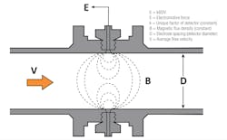
Electromagnetic flowmeters use a phenomenon known as Faraday’s Law of Electromagnetic Induction to measure flow. Faraday’s Law states that an electrically conductive fluid flowing through a magnetic field will generate an electromotive force (electric signal). The strength of that force is proportional to the velocity of the fluid moving through the pipe — the faster the fluid is moving, the larger the resulting electric signal.
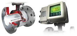
Engineers applied this physical law to create the practical design we now know as the electromagnetic flowmeter. Most meters on the market have the same basic construction — a meter body (sometimes known as a flow tube or detector) through which the process media flows, and an electronic converter, which turns the electric signal from the meter body into a useful piece of data.
The meter body itself is essentially a metal or plastic tube with a nonconducting/insulating liner that is mounted inline with the fluid being measured. Metal coils wrapped around the tube generate the necessary electromagnetic field, and electrodes mounted on opposite sides of the tube read the electric signal. This signal is directly proportional to the flow velocity.
The converter (sometimes called a transmitter, or just “electronics”), knowing the dimensions of the pipe and the strength of the magnetic field, processes and converts the electric signal to a useful output (4-20 mA analog output, HART or DE digital output, etc.).
This simple construction yields many benefits and options.
- Sizes range from very small (1/10-inch diameter) to very large (72-inch diameter and beyond), and a wide range of wetted materials are available, so mag meters can be used in almost all conceivable applications to measure everything from drinking water to highly caustic acids.
- Since the electrodes do not penetrate the fluid flow and the meter body is selected to match the surrounding pipe dimensions, there is essentially no pressure drop.
- There are no moving parts to wear down with use, so maintenance is minimized, and mag meters are bidirectional and can be used where flow is sometimes reversed.
- Manufacturers constantly improve both the hardware and software to optimize performance specifications such as turndown and accuracy.
Additionally, the mag meter market is large and mature, meaning there are designs readily available from multiple manufacturers, resulting in an open marketplace and cost-competitive solutions. However, there are some limitations that must be considered.
Practical considerations for flowmeter selection
Fluid conductivity
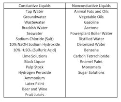
First and foremost, mag meters can only measure conductive fluids; they cannot measure vapors like steam or natural gas, or nonconductive fluids like ultra-pure water, animal fats and vegetable oils, or hydrocarbons (oil and gas). Four-wire mag meters can typically measure fluids with minimum conductivity of 3 microSiemens per centimeter (µS/cm). Two-wire mag meters, because of the lower available power, may require a minimum conductivity of 10 µS/cm.
Material and chemical compatibility
Second, the meter should be materially and chemically compatible with the process fluid moving through it. Many wetted materials (liners, electrodes and grounding rings) are available. A designer should never over-engineer a system — more durable and “exotic” wetted materials typically have higher costs — but should take care to consider the corrosivity, abrasiveness, pressure, temperature and other aspects of the media being measured.
Electrodes and grounding rings
The most common metals for electrodes and grounding rings are stainless steel, which can be used in most water applications (boilers, chillers, wastewater, etc.), and Hastelloy-C, a nickel-molybdenum alloy that can be used with seawater, bromine and many acids. More “exotic” metals like titanium, tantalum and platinum iridium can be used when stainless steel or Hastelloy are incompatible.
Liner material
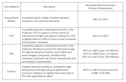
Most liners are made of fluoropolymers (plastic) such as PFA and PTFE that have good chemical and abrasion resistance and are suited for applications in heating and cooling, water and wastewater, pulp and paper processing, and food and beverage. Hard rubber liners can be used for fluids with larger, irregularly shaped solids. In the case of very aggressive slurries, ceramic lining can be used. As with electrode and grounding ring material, chemical compatibility should also be considered to avoid chemical corrosion.
Table 2 shows characteristics of various process wetted materials taken from reputable sources; consult a compatibility database or a materials expert before finalizing any designs.
Fluid velocity and dissolved solids
One must also consider the physical aspects of the fluid being measured when selecting materials. Mag meters can measure flow velocities greater than 0.1 m/s and less than 10 m/s (most manufacturers recommend velocity limits from 1 m/s to 5 m/s to avoid pressure loss from pipe friction and to reduce wear on the lining). In the case of slurries, flow should be reduced to under 2 m/s. In mining operations, for example, pulverized rock is mixed into water and transported through pipes. Large, abrasive particulates moving faster than 2 m/s can wear away the liner rapidly.
Typical and atypical process conditions
Other design considerations include whether the process will see significant temperature or pressure changes. Thermal cycling or rapid evacuation of a line for maintenance could “peel” or “blister” the liner away from the detector substrate; some mag meter bodies mechanically lock the liner to the substrate to protect against this.
Black liquor measurement in pulp and paper operations can be especially difficult to measure. During the paper-making process, a caustic material (known as white liquor) is mixed with wood pellets in a process called digesting. As the wood pellets are broken down, the pulp stock is separated out of the mixture and sent to the next process to be made into paper. The contaminated caustic that remains, now known as black liquor, is burned in a recovery boiler to become green liquor. The green liquor is recausticized to become white liquor again and is used in the next digesting batch. Measuring the flow of the black liquor can be difficult with traditional mag meters for two main reasons:
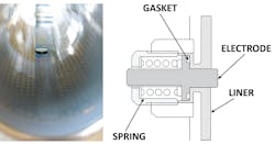
- Thermal effects: Thermal shock (large temperature changes in short time periods) can crack ceramic liners and deform PFA liners, which peel away from the substrate at the ends of the flow tube; high fluid temperatures can deform gaskets and cause leakage at the electrodes; and vaporized gas from the black liquor can even penetrate PFA liners and cause it to blister away from the steel substrate.
- Scaling can build up on relatively rough liners or on electrodes that are flush or slightly recessed into the flow tube wall.
Fortunately, engineers have solved these issues with special designs for difficult applications. Most conventional PFA liners have a profile roughness parameter Ra of 0.1 to 0.2; a polished ceramic liner can have Ra of 0.2 to 0.3. This may not seem like much, but scaling can happen on these relatively rough surfaces. Special mirror-finished PFA liners (surface roughness Ra of 0.03 to 0.08) can effectively eliminate scaling on the liner wall.
To prevent failures due to thermal effects, a variety of solutions exist. Special heating and aging steps to mechanically lock the liner to a metal punch-plate mitigate peeling and blistering, and high-compression reinforced springs can ensure a tight gasket seal at the electrodes. Adding vent holes in the flow tube allows vaporized gas to escape from the meter, rather than causing blisters and bubbles.
Placement in situ
Every application should be considered carefully, but overall, mag meters are not as sensitive to non-uniform flow as some other flowmeters — obstructions such as pipe bends and elbows and other instruments have minimal impact on the meter. Consequently, most mag meters can be placed as close as 3 pipe diameters upstream from a bend or other obstruction, versus a minimum 10 diameters for many other flowmeters. Table 3 shows recommended minimum required upstream and downstream diameter distances for the most common flowmeter types.
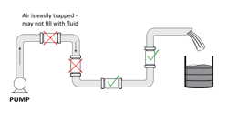
Distance from obstructions is not the only consideration when selecting where to place a meter, although mag meters require a full pipe to read properly. Ideal placement is in a vertical pipe with the process media flowing upward, as this ensures the pipe is full at the point of measurement. Meters can be mounted horizontally, provided the pipe remains full. They should not be placed in a section of pipe with flow moving downward — the “waterfall” effect in the pipe could result in pockets of air, and this would cause poor meter reading. Figure 6 shows proper mag meter placement.
Cost considerations
No discussion on flow measurement is complete without mentioning cost. Mag meter cost is “middle of the road” relative to other technologies — they are typically cheaper than Coriolis meters, more expensive than differential pressure transmitters and competitive with vortex and turbine meters. Cost increases with pipe diameter — the bigger the flow tube, the more material is needed. It is easy to compare prices of a mag meter versus Coriolis, DP flow or vortex technology, but unit price does not come close to telling the whole story. One must consider total installation cost — primary elements, wiring and conduit, energy to run the meter, and the cost of taking a meter out of service can dwarf the piece price. Be sure to consult a knowledgeable instrumentation and controls technician and a field instrument manufacturer to understand the total cost of ownership of various flow measurement techniques.
Conclusion
There is no single flow measurement solution for every conceivable application. Coriolis meters are accurate but can be expensive; vortex meters are durable but struggle at low flow rates; differential pressure flow measurement can be cost-effective but, by definition, requires significant pressure drop; and electromagnetic flowmeters avoid pressure drop but can only measure conductive fluids. Some operations require extremely tight flow rate measurement for chemical dosing or custody transfer. Other operations just need to prove flow, so a pump does not burn out. Many use the data to help with energy management. Experienced professionals should evaluate every application and develop a flow measurement strategy tailored to fit the information to be gathered and how it will be used. Mag meters cover a wide variety of pipe diameters and process media and provide important data at a reasonable price point. Once installed, they can provide years of reliable performance without disrupting a process. Simply stated, electromagnetic flowmeters are the workhorses of industrial and commercial fluid flow measurement and are a proper design choice for a huge variety of processes.
Francis “Mac” Kern is a regional sales manager for Azbil North America Inc. based in Denver, Colorado. He holds BSE-ME and BSE-IOE degrees from the University of Michigan at Ann Arbor and an MBA from DePaul University. Kern has worked in various roles at Azbil, with a current focus on digital marketing content management. He can be reached at [email protected].
Mac Kern | Western Regional Sales Manager — Azbil North America/VorTek Instruments
Francis “Mac” Kern is a Regional Sales Manager for Azbil North America, Inc. based in Denver, Colorado. He holds BSE-ME and BSE-IOE degrees from the University of Michigan at Ann Arbor, and an MBA from DePaul University. Kern has worked in various roles at Azbil, with a current focus on digital marketing content management. He can be reached at [email protected].
