A New Paradigm for Thermal Dispersion Mass Flowmeters
Since the publication of the American Society of Mechanical Engineers (ASME) standard on thermal dispersion mass flowmeters in 2011, there have been major advancements in the technology. A review of that standard and a discussion of technology advancements provide the background to understanding groundbreaking innovations in sensor design. That, along with a comprehensive algorithm facilitated by current hyper-fast microprocessors, has created a new paradigm for the measurement of the mass flowrate of gases by means of thermal dispersion technology.
The ASME Standard
In recognition of the widespread use of thermal dispersion mass flowmeters all over the world, the ASME published, in 2011, ASME MFC-21.2-2010, Measurement of Fluid Flow by Means of Thermal Dispersion Mass Flowmeters1. This ASME standard establishes a common terminology and gives guidelines for the description, principle of operation, selection, installation, and flow calibration of thermal dispersion flowmeters for the measurement of the mass flowrate of a fluid in a closed conduit.
History & Description
Thermal dispersion mass flowmeters measure the mass flowrate of fluids, typically gases, flowing through a pipe or duct. Their first general description is attributed to L. V. King who, in 1914, published his famous King’s Law2 revealing how a heated wire immersed in a fluid flow measures the mass velocity at a point in the flow. He called his instrument a “hot-wire anemometer,” and these instruments have been used in fluid mechanics research and as light-duty mass flowmeters and point-velocity instruments. It was not until the 1960s and 1970s that industrial-grade, metal-clad thermal dispersion mass flowmeters that could solve industry’s more rugged needs became commercially available.
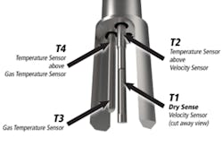
Thermal dispersion mass flowmeters measure the heat convected into the boundary layer of the gas flowing over the surface of a heated velocity sensor immersed in the flow. Since it is the molecules of the gas that bear its mass and carry away the heat, thermal dispersion mass flowmeters directly measure mass flowrate.
Typical gases monitored include air, methane, natural gas, carbon dioxide, nitrogen, oxygen, argon, helium, hydrogen, propane, and stack gases. Mixtures of these gases and mixtures of hydrocarbon gases are also included. Common applications are: combustion air; preheated air; compressed air; fluid power; boilers; electric power plants; cooling, heating, and mixing; drying of materials; food and beverage industries; natural gas distribution; aeration and digester gas monitoring in wastewater treatment plants; cogeneration with biogas; fuel gas; flare gas; semiconductor manufacturing; heating, ventilation, and air conditioning; single and multipoint stack gas monitoring; and chemical reactors.
Thermal dispersion mass flowmeters have two primary configurations: in-line and insertion.
- In-line flowmeters are applied to pipes and ducts with diameters typically ranging from about 10 to 100 mm (0.25 to 4.0 inch pipe sizes). Process connections include flanges, pipe threads, and compression fittings. Some manufacturers offer a built-in flow conditioner that reduces the length of upstream straight pipe required to achieve independence of upstream flow disturbances.
- Insertion flowmeters usually are applied to larger pipes, ducts, and other flow conduits having equivalent diameters typically ranging from approximately 75mm to 5m (3.0 inches to 200 inches). Compression fittings and flanges are commonly used process connections.


