Vent & Flare Gas Metering
Is there a requirement for onshore and offshore oil & gas exploration companies to monitor and report daily volumes of flare and vent gas under environmental regulatory mandates? The answer to that question is a definite yes—either by calculation or direct measurement—and environmental requirements figure to grow stricter going forward.
Why Flare Gas Monitoring Is Important Within the last decade of activity in the area of shale oil & gas exploration and extraction in the U.S. and Canada, regulatory agencies have clamped down on emissions and enforced rulings to ensure compliance.
When crude oil is extracted from shale formations and produced, there is a high content of natural gas that is entrained within the crude oil, and this gas rises to the surface.
The flares seen in the oil fields are vapors being burned off from various sources. One source is vent gas (final product) coming off of production tanks, sometimes referred to as tank batteries, which hold stabilized product to be loaded into trucks. The tanks are at atmospheric pressure and are vented to allow product to flow in and out. The vapor accumulating in these tanks and then vented must be captured and burned. This captured gas cannot be injected as re-pressurized gas back into the pipeline because there is a potential for air to flow back into the system.
READ ALSO: EPA’s Annual U.S. Greenhouse Gas Inventory Shows 3.4% Decrease In Emissions
The other source at the well site where gas vapors are consumed through flaring involves higher-pressure sources in the process. As the crude oil and natural gas mixture comes out of the well, the pressures can range from 100 PSI to 5,000 PSI. After separating the water and gas from the crude oil through a series of processes and then bringing the crude oil up to atmospheric pressure and stabilizing it, the gas is sent down to midstream operation for further processing.
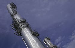
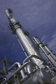
In this phase of the process, usually the gas is pressurized and volatiles are driven off and put directly into the pipeline, but the gathering system infrastructure still requires a flare to burn off hydrocarbons instead of venting directly to atmosphere. These flare systems consist of a flare stack and pipes that feed gas to the stack.
There are several reasons why it may be necessary to flare gas during drilling, production or processing. After a shale oil & gas well is drilled and hydraulically fractured, a temporary flare is utilized during well production testing. Testing is important in order to determine the pressure, flow and composition of the gas or oil from the well. Flaring at the well site can last for several days or weeks, as the pressures and flow of liquids and gas from the well are stabilized.
In the well site extraction process, there are typically one to six wells per pad, and each pad has a flare stack with piping sizes from 2” to 6”. In the gas-extraction process at the well site, the flaring of gas out of the stack must be monitored and recorded. It is of vital importance that the vented gas prior to the inlet of the flare should have a flowmeter to measure the flowrate and provide totalized daily flow. This information is required by the local, state, and federal environmental agencies for the purpose of knowing exactly what flows out of the flare and into the air space as VOCs (volatile organic compounds).
In April 2012, the EPA passed rules to address air emissions from all oil & gas exploration, production, processing, and transportation facilities. The mandate by environmental agencies like the EPA is through 40 CFR Part 98, Sub Part W, and it states that a direct measurement of the flow of this vented gas must be performed on a continuous basis. Throughout North America, there are many different shale oil & gas formations, such as the Marcellus and Utica shale in western Pennsylvania and upstate New York, the Eagle Ford in Texas, the Bakken formation in the Dakotas, etc.
By monitoring and recording flare gas flow, lease operators can ensure compliance with Green House Gas emissions and 40 CFR Part 98 subpart W.
The Challenge of Measuring Vent Flare Gas
With the range of flow technologies available on the market today, it is important to know which technology is the best choice for vent flare gas measurement. The flowmeter needs to be able to accurately measure over a broad range of flows from 1’ to more than 100’ per second, while at the same time accommodating changes in gas composition and not restricting flow.
The gas flowing in the flare line can be of varying composition with hydrocarbons from C2 through C6, which can change in their percentages based upon what happens at the extraction point. The flow of the gas is also quite low under stable, normal conditions, but upset conditions can occur causing the flow velocities to increase up to as much as 300 feet per second. This wide rangeability of flow, including pressure drops and varying gas compositions, can be a showstopper for most flow technologies.
One type of flow measurement method that performs reliably and accurately in vent flare gas applications is thermal mass technology. This technology operates on the constant temperature differential method and provides a direct mass flowrate measurement (standard volumes without pressure/temperature compensation). There are two RTD sensors, with one measuring temperature and the other that senses the flow. The temperature sensor measures the temperature of the gas and instantly corrects for changes in temperature. It then sets the temperature of the flow sensor to a precise value above that of the passing media. The accuracy of the flow measurement is based on the fact that all media conduct heat off of the sensor as a direct function to the mass flowrate.
Thermal mass technology has been around for many years, and over the last several years, there have been improvements made to the electronics and in sensor design. Even though both electronics and sensor design are a combined set, the design of the sensor or probe is particularly important. With various constituents in the vent flare gas stream, it is important to have a probe design that is of single-piece construction and easily maintained. Quick response to flow changes is essential in gas measurement, as is wide rangeability to support normal velocities of 2’ to 8’ per second and up to more than 100’ per second during upset conditions.
Another challenge of vent flare gas monitoring is that pressure drops can occur as the vent gas flows through the flare line, and these pressure changes can be challenging for flow technologies unless they are calibrated for upfront. Many flow technologies work well under predictable process conditions, such as flare safety systems within industrial plants, but upstream vented flare gas can be challenging for those same technologies.
Vented flare gas monitoring requires a technology that can effectively respond to pressure changes or drops, and support turndown ratios up to 100-to-1. These are the areas in which thermal mass technology excels. Further, thermal mass flowmeters are advantageous because they do not present an obstruction to flow stream and can accommodate virtually any line size. Thermal mass technology is easy to install using a process thread of ¾” NPT and, possibly, a hot-tap assembly. Either way, the installation is quick, and the start-up and commissioning cost is low.
There are a handful of flow technologies that have been used over the years to measure vent flare gas flows; Pitot tubes, orifice plates with pressure transmitters, mechanical turbine style, thermal mass, and a few others. Mechanical flowmeters, like turbines, have seals and bearings that can wear out over time. Further, if the media flowing through the turbine section has any particulate matter, this can foul a turbine flowmeter. The same can hold true for any flow technology that has a point of entry, like an orifice plate, which can potentially clog over time if the media has any build-up or coating potential.
In the case of the vent gas flare application at the wellhead, the vent gas can be ladened with sulfites and other particulates in the flare line. Having a single-piece constructed probe body with no openings or multiple sensor prongs can be a huge benefit when it comes to dealing with fouling media.
Some of the newer flowmeter technologies, like transit-time ultrasonic and Coriolis, perform quite well in vent flare gas applications. However, the price point for these meters is typically much higher than thermal mass flowmeters. Meanwhile, technologies like orifice plates with pressure transmitters and Pitot tubes can measure nominal or upset condition flows, but during the occasional upset condition, the wide dynamic flow range will prove difficult for these technologies to manage. In addition, deposits in the gas mixture can cause plugging problems with orifice plate and Pitot tube measurement devices—especially with sulfites in the gas.
When one looks at the typical vent gas flare at a well head site, all flows are typically below velocities of 300 fps with the high end measurable by thermal mass meters and even ultrasonic flowmeters. However, many flares are designed for worst-case events that could exceed this measurement capability. Other flow technologies can be utilized for vent flare gas applications, but they may require the use of multiple measurement techniques, which increases cost and usually requires more than one opening in the flare line.
All things considered, thermal mass flow technology offers an optimal and economical solution for vent flare gas measurement.
Jerry Boisvert is the sales and marketing directory for Thermal Instrument Company. Boisvert has worked in the level and flow instrumentation market for 31 years for companies including Siemens, Emerson Process, Magnetrol, Flexim, and a few others over that 31 year span. He has held various positions such as product marketing, applications engineer, business development, and regional sales. Boisvert can be reached at 215 355-8400 or [email protected].


