Compensating for Compressibility in Measuring Gas Flow
Unlike crude oil and other liquid fossil fuels, natural gas poses a challenge in monitoring the quantity of gas flowing through pipelines. While liquids do not compress, gases do, and the mass flowrate of gas being transmitted through gathering lines depends on both the pressure and temperature.
The bottom line is the volume of gas under one set of pressure and temperature conditions is not the same as it would be for the gas under different conditions. Why is this important? Without compensation for compressibility, readings taken by gas flowmeters can result in measurements—and costs to the buyer—significantly lower or higher than they should be.
The flow of gas in a system can be accounted for and reported in a number of ways, such as by volume, by mass flowrate, and by energy. Inline turbine meters can offer both reliability and accuracy in measuring gas flow when matched with a monitor capable of calculating and displaying results that have been adjusted for the nature of the gas, and importantly, the pressure and temperature.
Measuring Flow with an Inline Turbine Flowmeter
With an inline turbine meter, gas flows into the meter through a length of piping that helps to pre-condition the flow by reducing undesirable swirls and asymmetry. Where considered necessary, a flow straightener may even be installed in line, to create a uniform flow profile to the extent possible.
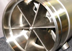
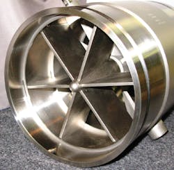
As can be seen in Figure 1, a rotor support within the turbine housing further conditions the flow and directs it through the blades of the rotor. High-precision ball bearings allow the rotor to freely rotate on the shaft.
The rotor’s rotational speed is directly proportional to the velocity of the fluid passing through the meter. The rotor itself incorporates magnets (or magnetic blades, depending on the design), while the housing is non-magnetic.
A proximity sensor (also known as a pickup coil) is located in line with the rotor and detects the electrical pulses generated by the ferrous rotor spinning through the magnetic field.
Each pulse represents a discrete volume of gas. The output frequency provides the indication of the gas flow rate, and the accumulated pulses over a specified time represent the total volume of fluid for that measurement period.
Need for Calibration
The flowrate of the gas through the meter cannot be determined accurately unless the meter is calibrated. The factory calibration determines the meter’s constant, known as a K-factor, which is then inputted into the gas monitor. Gas flowmeters measure the actual volume of gas passing through the meter per minute irrespective of pressure and temperature.1
The volumetric flowrate of a gas is often corrected to “standardized” conditions of pressure and temperature. While “standard” conditions can vary, depending on the definition, in the U.S. this typically means a pressure of 14.73 PSIA (pounds per square inch absolute) and a temperature of 60 F. The flowrate measurement is reported in standard cubic feet per minute (SCFM).
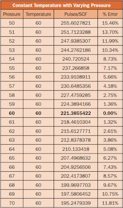
Compensating for changes in pressure and temperature is critical. Consider a meter system setup for flowing conditions of 60 PSIG (pounds per square inch gauge) and 60 F, and the line pressure decreases to 50 PSIG, while the temperature remains constant. The difference in SCFM between the two is more than 15 percent, which would cost the buyer more for the gas than it should. As Table 1 demonstrates, even a small variation in pressure will result in a surprisingly high error percentage.
Automation of the K-Factor
The K-factor is established by an initial factory calibration. In the case of a non-compensated flow monitor, any variations in pressure and temperature will result in manual adjustments needed to the K-factor. In order to maintain accurate flow measurement, users must monitor pressure and temperature and make corresponding adjustments to the K-factor. To eliminate these manual adjustments, some suppliers offer a flow monitor that automatically adjusts for any changes in pressure and temperature.
These monitors provide accurate flow measurement regardless of changing environmental conditions, in some cases supporting applications with pressures as high as 15,000 PSIG and temperatures between -350 F to 350 F with a standard accuracy of +/-1 percent over a flow range of 0.5 ACFM to 650 ACFM.
Final Notes
During the operation of a flowmeter system, the ability to obtain a readout — and to adjust for line pressure and temperature changes — is sometimes compromised by a lack of electric power. This issue is especially true along gas pipelines in remote areas. To overcome this limitation, some manufacturers have designed low-powered flow monitors, which can operate for up to on year on a single lithium D-cell battery.
It is important for users to recognize the effects of the compressibility of gas. As such, the quantity of a gas flowing through a gas flowmeter depends on the pressure and temperature. In order to ensure accuracy, any flowmetering system must employ a means to correct for these effects. Otherwise, the readout is certain to be in error and could be unnecessarily costing money. This is particularly crucial on wellhead production and in billing scenarios.
Kevin Clark is senior development engineer for Turbines Research & Development LLC. Turbine R&D is a subsidiary and the research and technical support arm of Turbines Inc., which serves a range of industries and applications, from oil & gas, to cryogenic liquids, to custody transfer.
Notations
- The measurement factor in the U.S. is known as the ACFM, actual cubic feet per minute. (Metric units are typically ACM/H, actual cubic meters per hour).


