Ultrasonic Flowmeter Provides a Novel Solution to a Complicated Slow-Flow Measurement
The following case study is a condensed version of a larger article that will appear in the November issue of Flow Control magazine.
While there are not many applications for measuring extremely slow flowrates, several of them are critical to the environment. One of the most important is tracking contaminants in groundwater. There are many sources of potential contamination—fertilizer run off, oil leakage, spills, coastal landfill seepage, and a variety of chemical intrusions—and the Environmental Protection Agency (EPA, www.epa.gov) mandates constant monitoring of groundwater where such contamination has occurred.
One company that offers these and other services is Coastal Monitoring Associates based in San Diego, Calif. The company is comprised of a team of engineers, scientists, and technicians who have developed new technologies for the monitoring and characterization of groundwater/surface water interaction. These technologies include rapid, direct-push, multi-probe mapping systems, as well as continuous-detection ultrasonic seepage meters with flow-proportional water sampling. The company’s services are used in assessment of coastal landfills and hazardous waste sites, contaminated sediment management, validation of sediment capping systems, and water management investigations.
Groundwater Seepage Measurement
One of CMA’s biggest successes is its patented methodology for ultrasonic offshore monitoring of contaminated groundwater seepage.
“When there’s groundwater flowing that’s discharging offshore, our clients often want to know the amount, or the flux, and how that would be passing through the sediment into the surface water,” said Ron Paulsen, hydrologist for CMA. “They often have to design a cap for these sediments to assure the contaminants do not seep into the surface water. To design the cap you have to know the force that affects the flux that goes through the sediment. That helps them determine the thickness and porosity of the cap.
RELATED: Clamp-On Ultrasonic Flowmeters Get Another Look
The seepage technology utilized by CMA is based on the time-transit ultrasonicgroundwater seepage meter. Three types of ultrasonic seepage meters are utilized depending on the requirements of the study—either the Ultra Seep (US), the Ultrasonic Buoy System (BS), and the Ultrasonic Submerged Flow-Only System (SFO). All three systems rely on the same principle and underlying hardware to detect seepage but provide different configurations for deployment. The U.S. system integrates the ultrasonic seepage meter system with a flow-proportional water sampling system. The BS and SFO systems are identical in theory of operation, but only measure the flow (no automated water sampling), and the BS battery and data logger are mounted remotely in a buoy, which can support up to two seepage meters. (A complete description of each meter technology can be found in the Groundwater Journal in articles by Paulsen et al. and Chadwick et al. (2003).)
“We basically adapt a flowmeter to an underwater housing and deploy it just offshore,” said Paulsen “We direct the groundwater through a funneling system that we implant in the sediment bottom.” From the funnels it’s piped through an underwater housing that has the flowmeter in it, which enables the accurate measurement of seepage flow, which can in turn be provided to clients.
Identifying a Flowmeter
“Ultrasonic seepage data for the US, SFO, and BS meters are processed to determine specific discharge rates,” said Paulsen. “Data from the three meter types are processed in essentially the same way. Raw data from the meter are recorded as a flowrate, generally in units of L/min.” These flow data are converted to specific discharge based on the geometry of the flow tube and seepage funnel as where Q is the flowrate measured by the ultrasonic flowmeter, and Af is the area of the funnel. “We have resolved the specific discharge down to 0.25 cm per day using a larger funnels capture area,” said Paulsen.
Central to this technique is the ultrasonic flowmeter. The flows are very modest—down to 5 milliliters per minute; to visualize just how modest that flow rate is, consider that a milliliter of water contains approximately 20 drops. If the water were coming out of a small tube at that rate, it would be flowing at about one drop per second. So it is critical to the whole operation to have an extremely sensitive and accurate flowmeter.
“When we did our research we found only one manufacturer who could measure low flows accurately,” said Paulsen. “Controlotron offered a meter called the Flow Tube that was ideal for our operation.”
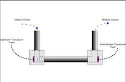
Conceptual diagram of the Controlotron Flow Tube design used for this slow-flow application.
The Contolotron meter consisted of a U-tube with a small down pipe positioned in a bored out plastic block, a cross pipe in another block, and another plastic block containing an up pipe. The metering method used time-of-flight ultrasonic technology to measure these very slow flow velocities and compute a volumetric flowrate. The two plastic blocks have an embedded piezo crystal in them that looked down the long pipe in the middle and measured slow flows accurately.
The system detailed here worked quite well, but then something unexpected happened that left CMA without a solution. Find out what this unforeseen obstacle was and how it was overcome in the full text of this article, which will appear in the November issue of Flow Control magazine. If you are not yet a subscriber to Flow Control magazine, click here to register for your free subscription now.
Jack Sineis a freelance writer specializing in environmental issues and the chemical, power, and HVACR industries. He can be reached at [email protected] or by phone at 845-831-6578.
