Level measurement in water and wastewater lift stations
Lift stations pump water and wastewater from lower to higher elevations to compensate for topographical changes. Most processing facilities are fed by gravity flow of the water and wastewater, so in locations where a change in elevation prevents gravity feed, lift stations pump the water to a higher elevation to increase the hydraulic head to provide reliable gravity flow into the facility.
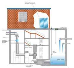
Water level in the lift station wet well or reservoir needs to be monitored (see Figure 1) to provide input to the pump, which pumps water out when it reaches a predetermined level. The level measurement also turns off the pump at a minimum level to prevent dry run damage.
Wet wells can be difficult environments for instrumentation because high humidity and condensation are typical. Heavy coatings and vapors are capable of coating or corroding mechanical level measurement devices, leaving them inoperable. Technologies that do not contact the material being measured should be considered.
Historically, level measurement in lift station wet wells has used several technologies, including floats, submersible hydrostatic and noncontact ultrasonic instruments. These technologies can be effective when properly selected and maintained. This article looks at each and considers the positive and negative points.
Figure 1. Typical lift station. Water enters the wet well from the right. A radar instrument monitors the level. When the level gets high, the controller starts the pump to lift liquid to a higher elevation and empty the wet well.
Traditional technologies
For decades, float switches have been used for wet well level measurement. The advantages of float switches are their low cost and simple operation. Typically, two or more floats are used, with one acting as a high-level, pumpon and another float acting as a lowlevel, pump-off indicator. While floats have advantages in cost and simplicity, they can fall short in several ways.
Depending on the type of float, the linkage or cable tether can foul or hang up. Floats can sometimes leak and cause buoyancy loss. In wastewater applications, coatings on the float can cause it to sink. When using floats for wet well applications, regular maintenance is extremely important.
Level switches are often used as highlevel backups for continuous level transmitters to indicate if the well is close to overflowing. Since the high-level switch is only reached in "upset" conditions, floats work fairly well as high-level switches.
Submersible hydrostatic level transmitters operate on the water’s head pressure. A diaphragm in the transmitter is subjected to the water column on one side and referenced to atmosphere on the other side. Increases and decreases in level deform the diaphragm and cause changes in a capacitance bridge circuit, which is then converted to an output.
Submersible transmitters have several advantages. They can be preselected for the applicable range of level measurement. For example, the transmitter may be ranged from zero to 30 feet of water. Since they are preranged, calibration is not required. Submersible transmitters also have no moving parts to hang up or wear out.
Still, it is important to make sure the diaphragm does not become clogged with silt or other solids since clogging will affect accuracy. Heavy buildup can prevent the diaphragm from reacting to water level changes. When using submersible transmitters in applications in which silt or solids are present, choose a transmitter able to tolerate these applications. A transmitter designed for water with solids will have a cover over the diaphragm that allows for easy cleaning, but it is important not to damage the diaphragm when cleaning.
Ultrasonic instruments are commonly used to measure wet well water level. Ultrasonic instruments operate based on the time of flight principle (ToF). An acoustic pulse is sent to the surface of the water being measured and is reflected back. The time it takes to reach the water and return provides the distance to the water, which is converted to a level signal. One of the big advantages of ultrasonic level devices is that they are noncontact. That is, the transducer sending the acoustic pulse does not come in contact with the water, providing a cleaner application for sewage wet wells.
However, ultrasonic instruments are not immune to problems. Humid wet well conditions can cause condensation to form on the transducer face, which can attenuate the acoustic energy and limit the range. In some cases it can cause a near-field fault. Confusing acoustic reflections caused by structures in the wet well such as ladders, pump columns, cables, etc., must be taken into consideration and avoided or mapped out if the ultrasonic device used offers this feature.
Another concern is splashing on the transducer, which can leave residue capable of attenuating the acoustic energy and can require cleaning. In sewage wet wells where methane can be present, ultrasonic instruments experience another problem. The speed of sound is faster in methane than it is in air. This will cause errors in level measurement, resulting in the level appearing higher than it actually is.
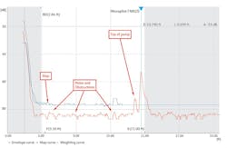
Figure 2. When a new or replacement radar level instrument is installed, its sophisticated mapping program detects all internal obstacles such as pipes and ladders. Like configuration, the mapping function can be accomplished remotely via the Bluetooth interface.
Radar level measurement
A recent trend in level measurement for lift station wet wells is radar technology. In the past, radar transmitters were considered too expensive for use in wet wells, but recent developments in electronics have allowed for new offerings in the $1,000 or lower range. Radar transmitters offer several advantages over traditional wet well level technologies.
First, like the ultrasonic instrument, radar is a noncontact technology that uses the ToF measurement principle. An electromagnetic pulse is directed to the surface of the material being measured. The energy is reflected by the dielectric property of the water. Similar to ultrasonic, the time taken to reach the water surface and the reflection to return are measured, providing distance to the water’s surface which is then used to calculate the level.
Along with the advantages of noncontact measurement, the transmission of electromagnetic energy is not affected by vapors or steam in the air space above the water, which is a decided advantage over ultrasonic level technology.
New radar antenna designs provide wetted parts of all-Teflon with a concave surface. These concave antennas are designed to shed condensation buildup on the antenna face, which prevents attenuation of the electromagnetic signal. In sewage wet well applications, the Teflon helps prevent coatings from adhering to the antenna when water splashes solids.
When selecting a radar unit for mounting inside a wet well vault, the transmitter may experience submersion in extreme conditions. For this reason, selecting an encapsulated transmitter that meets IP68 (protected against temporary immersion) is recommended.
Map it out
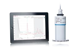
A major advance in new radar units is the simplicity of commissioning and mapping. The setup program can be accessed via Bluetooth and executed on a smartphone or tablet (see Image 1). This is a great advantage over older units, which required commissioning through a push-button human machine interface (HMI) or opening the housing and connecting a cable to a laptop with a modem.
The radar transmitter may be located in an installation that is difficult to access. This is particularly true of water and sewage wet wells in which the radar may be inside a concrete vault. Trying to reach these units for access to the HMI or to connect a cable to a modem may require a confined space permit. With Bluetooth, it is usually a simple matter of opening the manway.
New radar technology offers sophisticated mapping programs that allow the transmitter to ignore internal obstructions such as ladders, pump columns, cables and baffles. While these mapping programs are sophisticated, they are much easier to implement than previous mapping programs from even a few years ago. If the wet well is empty or the level is at its lowest point, simply executing the mapping routine is all that is required. The radar transmitter does all the work (see Figure 2). In situations where the tank is not empty, determine where the level is and then map to a few inches above the actual level.
Summary
Many ways exist to measure the water level in lift station wet wells. Selecting the technology able to provide the most reliable level measurement with the least maintenance should be the goal. While traditional technologies can provide reliable measurement, new lower-cost radar transmitters should be considered. The advantages gained in performance and reliability along with the ease of commissioning are significant.
Bill Sholette is the Northeast region level product manager for Endress+Hauser.


