Level measurement with time domain reflectometry guided radar offers advantages
Level measurement of tanks and silos is a critical part of the processing industries. Of the many available level measurement technologies, time domain reflectometry (TDR) guided radar stands out for its accuracy, reliability and safety. Now, new technology is available with a powerful 2 gigahertz (GHz) signal — the strongest signal for low dielectric applications — and a variety of probe options to meet application and process-specific needs. The devices come in compact and remote versions and are equipped with new features that promise even more accurate level measurement.
Ensuring level measurement accuracy and reliability
Continuous measurement of level, distance, volume, mass or liquid-liquid interface is critical for the process industries. For maximum accuracy and reliability, operators should take several different measurements on each tank — one continuous level measurement, four switch points (low, very low, high, very high), and one local measurement of the level.
A variety of level measurement technologies are available, including TDR guided radar, frequency-modulated continuous wave (FMCW) radar, ultrasonic, displacer, potentiometric and hydrostatic pressure.
Selecting the right instrument is based on the dielectric constant of the headspace (Ɛr) and reflectivity of the medium in the tank. TDR guided radar is considered the best option for high-pressure/high-temperature applications, very low dielectric media, heavy steam applications, and for measurement of the interface between two liquids. The Ɛr influences the reflectivity of the electromagnetic pulse, and the Ɛr is also frequency independent. Installation details are also critical elements in selecting the right instrument. The tank/silo design, nozzle dimensions and process connection information (size, pressure and temperature) are key items to be considered.
With TDR, electromagnetic pulses are emitted at the speed of light and guided along a probe. Each pulse is reflected with an intensity that depends on the dielectric constant of the product. The distance is calculated by measuring the transit time of the pulse, and this distance is then converted into the tank’s level.
The TDR measurement principle was originally developed in the 1990s for use in cable testing. Companies used the method to troubleshoot signal break issues with underground telephone, telecommunications and electricity cables. When a cable was broken, the electromagnetic technique was used to determine the breaking point. The difference in the time between emission and reception was shorter at the break, enabling engineers to quickly find the location of the broken cable. Using the formula in Figure 1, engineers could pinpoint the location of the break to a very specific distance from where they generated the signal.
KROHNE was a pioneer in adapting this TDR measurement principal for use in level measurement of tanks. Engineers reasoned that if distance could be measured by using a cable, why not place the cable directly into a tank to determine its level? The company produced the market’s first guided wave radar transmitter level measurement device in 1996 and has since expanded the technology for use in measuring air, solids and liquid levels in tanks.
Advantages of TDR level instruments
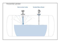
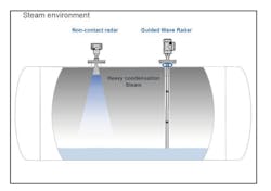
TDR level instruments have several advantages over other non-contact radar options, especially for tanks with a horizontal cylinder shape and in environments with heavy steam or condensation.
When using a non-contact radar, a horizontal cylinder can create a signal disturbance because it multiplies reflections. When the liquid level is at low or very high levels, the non-contact radar signal can be disturbed by multiple reflections. Using guided radar avoids this issue, because the signal always stays along the line of the probe.
In applications with high levels of steam or condensation, non-contact radars using horn antenna can result in signal noise issues, with the signal transmitting slower and slower. By contrast, TDR guided wave radar is less disturbed by steam — the signal stays strong from the process connection all the way to the probe end. This option provides the full energy of the signal from top to bottom of the tank.
Selecting the right TDR instrument
KROHNE offers a variety of TDR instruments in its OPTIFLEX product portfolio for level and interface measurements (those that measure levels of interface between two liquids in the tank). Different models have been developed for applications processing liquids with hygienic requirements, solids from granulates to powders, liquids in storage and process applications, and liquids at high temperature and pressure.
The new models include a powerful 2 GHz signal for a more accurate level measurement and smaller dead zones. They also offer the strongest signal for low dielectric applications. Loop power compact (C) or remote (R) versions are available for all models. Each model offers level or interface measurement without additional charge (except the OPTIFLEX 1100).
Ceramic process sealing (single or dual for more safety features) is also offered. A new multi-variable switch output has been incorporated in the housing, which reduces wiring costs by providing information on level, interface, dielectric, volume, diagnostics status and SIL 2/3. Finally, the devices include a new interface reverse measurement for measuring the interface in a vessel containing two liquids. In most measurements, the low dielectric is the upper liquid, and the high dielectric is the lower liquid. With the new reversed probe, users can measure the interface when the upper liquid is the high dielectric and the lower liquid is the low dielectric.
The instruments are available with three different probe types. The most common is a single probe (rod or cable). Also available are twin probes (rods or cables), which reduce the signal diameter to minimize disturbances in a tank. The third option is a coaxial probe, in which a rod is protected by a tube to ensure that the entire signal stays inside the tube. With a coaxial tube, no obstacles located inside the tank (for example, a ladder, level switch or heating coils) will disturb the measurement.
Application examples
As noted, selecting the right instrument must consider the dielectric constant and reflectivity of the medium in the tank as well as the tank/silo design, nozzle dimensions and process connection information.
- For example, for level measurement at a water purification system (skid), the OPTIFLEX 1100 C was used with Ø2 millimeter (mm) and 0.08-inch single cable probes.
- For level measurement of pharmaceuticals mixed with pure water stored in vertical cylinder tanks with 4-foot agitators, the operators selected an OPTIFLEX 3200 C with stainless steel housing and a 0.32-inch single rod probe.
- The OPTIFLEX 6200 C was selected for level measurement of hydrated lime (powder) at a desalinization plant using vertical cylinder silos.
- At a waste treatment plant with a 6-foot vacuum tank holding cleaning water containing small amounts of acids and suspended particles, operators opted for an OPTIFLEX 7200 installed on stilling wells inside the chambers.
- For level measurement of sugar condensate at a sugar refinery, an OPTIFLEX 7200 F (remote) with 4-foot (1.2 m) probe was selected.
- A final example is level measurement of softened water (alkaline) in industrial boilers (LP), where the OPTIFLEX 8200 C with single ceramic process seal system and coaxial probe was selected for the 5-foot (1.5 m) horizontal cylinder tank.
Signal strength and options for wide range of applications
For continuous measurement of level, distance, volume, mass or liquid-liquid interface, new OPTIFLEX TDR technology offers the signal strength and probe options to meet a wide range of application and process-specific needs.
Gilles Knobloch is the business development manager at KROHNE Group.


