PART I: Basics of Specifying the Correct Sight Flow Indicator
I’ve been working in the process industry for a long time, and every now and then I come across a gem of information and try to pass it on. Here I’ll try to tell you a bit about how to select the correct sight flow indicator.
Installed in pipes, these relatively simple devices let you see the direction and rate of liquid, gas or powder flows through pipelines. The devices also let you observe other important attributes of process fluids, such as color and clarity. Sight flow indicators feature a cast-metal body with one or more viewing windows that seal with gaskets.
Before specifying a sight flow indicator, it is first helpful to have some information about the devices under your belt. There are two main types:
View-through flow indicators have two opposing windows, letting you see the flow of fluid lighted from behind with ambient lighting or with an attached light. The units are suitable for high temperature and harsh fluid applications. They are available with a Teflon lining for corrosive applications. They come in standard lengths and are generally flange-mounted and selected according to standard ASME flange size.
Additionally, the view-through flow indicators can be fitted with indication devices, such as flappers, flutters, drip tubes, balls, and rotors.
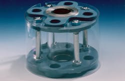
Full-view flow indicators pass fluid through a glass cylinder so the fluid is visible from all angles (i.e., 360 degrees). This lets ample ambient light illuminate the flow. The devices work well for observing process fluid for clarity, color, and foam, as well as for the presence of moisture.
RELATED: How Strong is Boriosilicate Sight Glass
The full-view flow-indicator suits lower-pressure systems with moderate flowrates, and they must be installed on pipes where there is minimal mechanical strain. Some versions are constructed with a cylindrical shield having windows; this type handles mechanical strain better. Full-view flow indicators are selected according to standard NPI sizes or standard ASME flange sizes. Many people don’t know that, unlike view-through flow indicators, they can be ordered in custom lengths.
Specifying the correct device for your application entails following a few steps. First, define the process to be observed, including temperature, pressure, physical attributes of the process media, flow direction, and any sanitary requirements. This data will tell you what kind of device to select. Last, choose the materials for the body, gaskets, and glass that are compatible with your process media.
In my next post, I’ll cover the types of indication available.
David G. Star is president and CEO of L.J. Star Incorporated www.ljstar.com, a supplier of sight glass and sight-flow indicator products, and he is the owner of Tank Components Industries, a manufacturer of tank heads and related process vessel components.


