How to set up a back-pressure regulator in an analytical sampling system
Many common system design errors can render a back-pressure regulator useless. System designers may overlook the importance of an upstream flow restrictive device, allow too much flow through the analyzer or place a pressure-reducing regulator in series with a back-pressure regulator with no flow resistance between the two devices.
To help avoid these errors, this article reviews how to properly set up a sampling system using a back-pressure regulator.
Setting up a back-pressure regulator
A back-pressure regulator controls inlet pressure and is typically mounted at the end of a line. It is the opposite of a pressure-reducing regulator, which controls outlet pressure and is used at the beginning of a line. Both types operate by attempting to balance forces that result from system pressure, with the loading force in the spring created when establishing the set pressure. When external pressure rises or falls, this balance within the regulator is upset, forcing the regulator valve to move either closer to or further from the seat. The valve’s movement allows more or less pressure and flow across the seat until the regulator re-establishes a balance of forces.
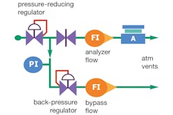
Figure 1 illustrates a typical back-pressure regulator setup for an analytical sampling system. The regulator operates by diverting any sample line flow not used by the analyzer (see A in Figure 1) to a bypass vent. The regulator changes the amount of diverted flow as the source pressure fluctuates, maintaining a constant pressure at the regulator inlet and a constant flow through the analyzer.
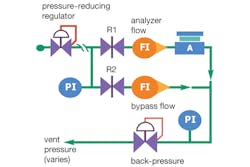
Figure 2. This figure illustrates a common design error in which a pressure-reducing regulator and a back-pressure regulator mounted in series compete and therefore manage pressure ineffectively.
To effectively manage inlet pressure, a back-pressure regulator requires a flow-restrictive device — typically a needle valve — mounted upstream (see R1 in Figure 1). This flow restrictor allows a set amount of flow, at a given pressure drop, to travel through the sample lines. When the pressure at the outlet of the flow restrictor is too high, for example, the regulator allows more flow to pass through to the vent, increasing flow through the restrictor and causing more pressure drop.
Unfortunately, system designers often omit the flow restrictor, erroneously thinking the back-pressure regulator can directly control the upstream pressure. Without the restrictor, no change in pressure occurs when system flow changes. Because it receives no feedback in the form of an inlet pressure change, the regulator continues to increase flow in a vain attempt to reduce its inlet pressure, wasting process fluid. This may result in the regulator being wide open.
Another common design error is allowing much flow through the analyzer restrictor (see R2 in Figure 1). Doing so will cause the inlet pressure of the regulator to drop below its set pressure. Then the regulator will shut completely, with no vent flow. For effective control, the upstream flow restrictor R1 must be set low enough to allow some flow to go through the regulator, even at the maximum analyzer flow rate.
To set up the system in Figure 1, start by closing R2; adjust R1 to provide a bypass flow sufficient for the desired analysis response time; and then adjust R2 for the desired analyzer flow. The bypass flow will automatically drop by the same amount. If necessary, slowly open R1 until the bypass flow is at least as fast as the analyzer vent flow. This will allow the regulator to control its inlet pressure when the source pressure changes. If the source pressure is expected to vary widely, adjust R1 to generate a small amount of bypass flow at the lowest anticipated source pressure.
Because the back-pressure regulator is controlling the bypass flow, do not install a needle valve or other restrictive device in the bypass vent line. However, a bypass flowmeter without a needle valve (see the lower FI in Figure 1) is useful to confirm the regulator is passing some flow and is controlling its inlet pressure.
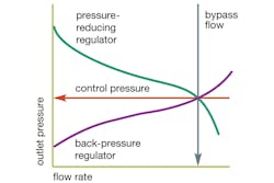
Figure 3. The system design in Figure 2 causes the two regulators to eventually hold an intermediate control pressure between their setpoints — but at a high flow rate.
Using pressure-reducing and back-pressure regulators in series
Some sample system schematics place a back-pressure regulator immediately following a pressure-reducing regulator, as shown in Figure 2. This is a common design error because two regulators cannot control the same pressure; one of them must lose.
Consider what happens when the setpoint of the back-pressure regulator is higher than the pressure coming to it from the upstream regulator. The back-pressure regulator tries to increase its inlet pressure by restricting the flow — but nothing happens. As the flow falls, the upstream regulator holds the pressure reasonably constant, and as a result, the back-pressure regulator ends up fully closed. It is now a redundant component and the pressure-reducing regulator is in control.
Now suppose the back-pressure regulator has the lower setpoint. If its inlet pressure is too high, the regulator opens to increase the flow. But as the flow rises, the pressure comes down slowly; it can only fall at the rate of the upstream regulator’s droop curve. The flow rate increases drastically, pushing the back-pressure regulator up its accumulation curve and increasing its inlet pressure.
What happens next depends on the settings of the two regulators.
If the two settings are close, the flow rate rises until the droop pressure out of the first regulator matches the accumulation pressure into the second one. The entry fee for this pneumatic tug of war is a very high flow rate. Figure 3 illustrates this point: The bypass flow rate depends on the difference between the two setpoints. It rises until — at some pressure between the two setpoints — the two regulators declare an uneasy truce. When upstream pressure changes or flow to the analyzer varies, the two regulators try to hold an intermediate pressure between their official setpoints, but with uncertain results.
Figure 4. Mounting a pressure-reducing regulator and a back-pressure regulator in series requires a flow restrictor (R2) between the regulators to ensure effective pressure and flow control.
If the two setpoints are further apart, the flow rate will rise until that regulator is no longer in control. One will now control the pressure and the other one will merely be a flow restrictor. In this case, the bypass flow may be very high, and droop or accumulation will be severe, compromising the controlling regulator’s ability to manage pressure.
It is possible to have two regulators in series if a flow restriction is placed between them (see Figure 4). With the correct settings, both regulators are fully in control and the pressure is constant at each end of the two flow restrictors. With this consistent differential pressure, the flows will be steady while shielding the analyzer from variations in source and vent pressure.
Protecting the system
Analytical sampling systems that feature back-pressure regulators must be designed carefully to avoid compromising the regulator’s ability to control pressure. If pressure is too high, the analyzer could be damaged. If it is too low, an unacceptable analysis time delay may occur. Following the guidelines above will help designers avoid some common design errors to ensure the sampling system delivers reliable, consistent pressure and flow control through the analyzer.
Reference
- This article was adapted from "Industrial Sampling Systems: Reliable Design and Maintenance for Process Analyzers" (2013), a process sampling textbook authored by Tony Waters and published by Swagelok Company. For more information, visit industrial-sampling-systems.com.
Randy Rieken is market manager for chemical and refining for Swagelok Company. He can be reached at [email protected].


