How to save thermowells from vortex-induced vibrations and mechanical fatigue
The helical design has long been used to dampen flow-induced forces in a variety of applications. It also helps control vortex-induced vibrations in thermowells, a problem that plagued a major petroleum company. The goal: To find an efficient, economical and long-lasting alternative to using support collars to stabilize its thermowells.
Thermowell reliability
Temperature is the most measured parameter across industries and sectors. The variety of temperature sensors includes thermocouples, resistance thermometers (RTDs) and bimetal thermometers. These instruments can be used as-is or with a simple metal sheath. However, in particularly harsh environments, sensors need a better buffer.
Thermowells are used worldwide to protect temperature sensors from high process pressure, aggressive media and the like. Most thermowells are machined from solid bar stock, usually stainless steel or other corrosion-resistant alloys — depending on the process conditions. The sensor is inserted into the bore of the thermowell, which, in turn, is placed directly into the process stream. Heat transfers from the fluid to the thermowell wall and then to the temperature sensor.
Thermowells have another advantage: They allow operators to easily replace a temperature measurement sensor. Remove, replace and it is finished.
These thermowells are robust, reliable and long-lasting. However, they sometimes fail because of mechanical fatigue. How and why does this happen?
The trouble with vortices
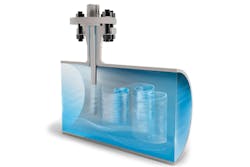
When any object is inserted into moving liquid, the flow can produce hydrostatic and aerodynamic forces around that object. Under certain conditions, the fluid that flows around the cylindrical thermowell creates a wake. This wake generates vortices that rotate in opposite directions and then detach (shed). The phenomenon, as most students of fluid dynamics know, is the Kármán vortex street.
Vortex shedding creates a periodic lift force normal to the direction of the flow and a periodic drag force inline with the flow. These forces cause the thermowell to shake. The frequency of vortex-induced vibrations (VIV) is determined by the frequency of the wake, which, in turn, depends on the thermowell’s diameter and the fluid’s velocity.
Shedding frequency increases linearly with fluid velocity, but the induced forces increase with the square of the velocity. As a result, even small increases in fluid velocity can result in much stronger forces. When the shedding frequency approaches the thermowell’s natural frequency, the thermowell could "lock in" and go into resonance — thereby rapidly increasing the force of the vibrations. The more a bluff body is exposed to vibrations, the sooner it could fail because of mechanical fatigue. For a thermowell, the failure usually occurs at the base, where the bending stress is strongest.
Wake frequency calculation
When determining which thermowell design to use, it is important to consider its potential for VIV within a particular application. To do that, find the wake frequency calculation (WFC) of a thermowell per ASME PTC 19.3 TW-2016.
This calculation takes into account resonant frequency, static stresses, dynamic stresses and limits in permissible pressure among other things. The calculation is divided into dynamic and static calculation results. The evaluation of the dynamic results is made using the damping factor NSC. (The Scruton Number NSC has a direct relationship to the permissible frequency ratio rmax from the vortex-shedding frequency fs to the natural frequency fn.) Simplified, a characteristic value for gaseous media is NSC > 2.5; fluids typically have an NSC < 2.5. The static results of ASME PTC 19.3 TW-2016 are generated from the maximum permissible process pressure (dependent on the process temperature and the geometry of the thermowell) and the bending stress in the area of the thermowell root.
If the WFC passes, all is well. If the WFC fails, the user must alter either the medium (impractical and undesirable) or the thermowell (much more doable).
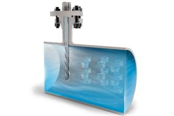
The helical strakes of this thermowell stem break up the flow and impede the formation of defined vortices, avoiding vibration excitation and, as a consequence, no resonance of the thermowell occurs.
Helical thermowells: Proven concept, new application
Scientists have long known that a helical design is good for controlling flow-induced forces. For decades, helical strakes have helped reduce vortex-induced vibrations in many applications, including chimney stacks, car antennas, offshore risers and suspension bridge cables.
Using this same concept, thermowell stems with helical strakes break up the process fluid flow and hinder the formation of Kármán vortex streets. The vortices found behind helical thermowells are small and weak. The amplitude of the diffused VIV is considerably reduced and does not excite the thermowell. With no excitation, thermowell resonance is not a risk.
A thermowell with a helical design can reduce the amplitude of oscillations by more than 90 percent while still allowing the maximum permissible pressure load using the original stem’s dimensions. As with conventional thermowells, these innovative fittings are easy to install. Operators do not need to tweak the length or diameter, or go through the time and expense of retrofitting thermowells with support collars.
The helical design can be used in all solid-machined thermowells with several process connections, including flange connections, Vanstone design and weld-in or screwed process connections. This type of thermowell is particularly well-suited for petrochemical processes, on/offshore applications and plant construction. It is also recommended for critical measuring points and high process loads.
Switching from smooth to helical: A case study
The petrochemical industry relies on thermowells to protect temperature sensors from the harsh conditions found in pipelines. At the same time, the thermowells themselves must be protected from the mechanical fatigue that comes from vortex-induced vibrations. What is more, the adjustments that are effective for one flow condition may not be sufficient for another.
Crude units, for example, work with liquid and vapor. Each phase has its own velocity, with the vapor generally moving faster than the liquid through a pipe. That is why it is possible for a thermowell to pass the wake frequency calculation in the liquid phase but possibly fail in the vapor state.
The usual first step to shrinking VIV is to shorten the stem length (see sidebar). If that does not help, changing the root or tip diameters might succeed in reducing the wake frequency. The usual last resort is to retrofit a thermowell nozzle with a support collar — an expensive and time-consuming process, especially when one considers the number of thermowells that a typical petrochemical plant uses. The advantage, though, is that support collars allow thermowells to pass WFC.
For one petroleum company, changing the standard thermowells’ dimensions did not sufficiently reduce VIV in its crude units because of the high velocity of the process. Support collars proved to be a good solution, but only for a while. But when the engineers upgraded a unit to increase its capacity, the thermowells attached to the piping were exposed to greater velocity and, thus more VIV. The result? The instrumentation failed calculations. To pass WFC, the engineers realized they would need a new set of nozzles to fit new support collars because the existing nozzle necks were badly welded. This option would require extensive — and expensive — on-site machining.
And this was just one unit. Future capacity increases in other units would lead to similar failed calculations and necessitate retrofitting.
The petroleum company asked a measurement technology manufacturer for suggestions. After analyzing the specific conditions of the crude unit, the manufacturer suggested switching to a thermowell with helical strakes. The new instrumentation with a helical design accomplished the client’s four goals:
- Pass WFC for the current capacity increase.
- Leave room for future velocity increases and capacity upgrades.
- No need for expensive, time-consuming work on-site to fix nozzle issues or install support collars.
- Provide a fast response time by using a standard tip diameter rather than one with a larger diameter.
In the best possible world, a thermowell protects the sensitive temperature sensor, has a short response time, and is fast and inexpensive to install. It also needs to pass its WFC. A helical design on the thermowell stem provides all that — and more — for the highest process loads in the oil and gas industry.
4 traditional methods for reducing thermowell vibrations: Pros & cons
Changing the structural design of a thermowell can reduce the effects of vortex-induced forces. Engineers can make the following adjustments:
- Shorten the insertion length. A shorter unsupported length increases the strength of the thermowell, making it less likely to vibrate. This method is an easy fix and, therefore, is the first step taken to pass the WFC. CON: If the vibration is very strong, the length may have to be trimmed so much that it becomes too short to reach the process medium.
- Increase the root diameter. A change in the thermowell diameter affects its natural resonance frequency. This is the second step to resolve a WFC fail if a shorter length does not do the job. CON: The root diameter may have to be enlarged so much that it no longer fits into the nozzle of the thermowell connection.
- Increase the tip diameter. A larger tip diameter reduces the thermowell’s vortex-shedding frequency. This is the third step to resolve a WFC fail if the above two methods do not help. CON: The tip may have to be widened so much that it no longer fits into the nozzle of the thermowell connection. An increased tip diameter also leads to a longer sensor response time.
- Add a support collar. To stabilize a thermowell stem, technicians could fit a metal ring inside the flange nozzle. This is the measure to take if none of the above methods sufficiently reduces vibrations. CON: Because adding a support collar requires extensive on-site machining, this process is expensive and time-consuming.
Adam DeLancey is Electrical Temperature Measurement (ETM) Center of Excellence (CoE) product manager at WIKA Instrument. He joined WIKA in 2004 after studying engineering design and drafting. After serving as product manager for WIKA Canada for several years, DeLancey transferred to the CoE for ETM covering the Americas, supporting manufacturing and sales with engineered ETM solutions. He focuses on special applications for temperature measurement including tubeskin and multipoint products.


