In many temperature measurement points, a thermowell is used to protect the sensor from process conditions. Since it is the only part of the instrumentation that comes directly into contact with the process medium, it should be designed to withstand all expected stresses and forces. Unfortunately, thermowell design is often overlooked.
To help with thermowell design, ASME recently updated the Performance Test Code (PTC 19.3TW) standard on thermowell calculations. The ASME PTC 19.3TW-2010 standard covers only thermowell calculations and is a vast improvement to the short section on thermowell calculations in the overall temperature measurement standard, ASME PTC 19.3-1974. The three most notable changes are inclusion of the in-line resonance condition, calculation of the Strouhal number, and improved natural frequency calculations.
1. Inclusion of the In-Line Resonance Condition
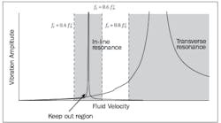
The 1974 standard only considers vibration or oscillation in the direction transverse or perpendicular to the pipe. The 2010 standard includes vibration in the direction in-line with the pipe. This creates a new resonance region when evaluating the wake frequency ratio (wake frequency vs. natural frequency).
Subsequently, the wake frequency ratio limit for liquids is reduced to 0.4 from 0.8. For gases, the area between the two resonance conditions (0.6 2. Calculation of the Strouhal Number The calculations expressing the correlation between the two numbers are based on test results of smooth and rough cylinders in different flow conditions. For conservative results, the Strouhal number curve in the PTC 19.3TW standard follows the rough cylinder results. 3. Improved Natural Frequency Calculations Old Natural Frequency Calculation
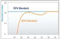
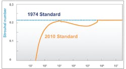
The Strouhal number is a key component of the wake frequency calculation. It describes oscillating flow and varies depending on flow conditions. The 1974 standard used a set Strouhal number of 0.22. The 2010 standard uses a variable Strouhal number that is dependent on the Reynolds number, which describes flow conditions.
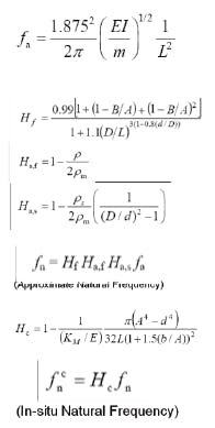
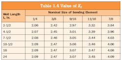
In the 1974 standard, the natural frequency calculations were very simple tables from which you could interpolate and extrapolate results.
The 2010 standard has detailed calculations that take into account real world effects. In fact, there are several correction factors, including the beam correction factor and sensor mass factor. These factors are applied to a new, improved natural frequency calculation. This provides more accurate wake frequency ratio results.
New Natural Frequency Calculation
Other Considerations
The standard has many more changes and improvements. Therefore, users should consider other components of PTC 19.3TW before starting the thermowell design process.
The standard explicitly states that velocity (or frequency) collars are not recommended as a means of immersion length reduction.
“Support collars or other means of support are outside the scope of the standard. The use of support collars is not generally recommended, as rigid support can be obtained only with an interference fit between the support collar and the installed piping.”1
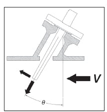
Angled and elbow installations are covered by PTC 19.3TW. Both installations decrease the cross tip velocity and reduce the wake frequency ratio. The maximum angle of installation covered by the standard is 30 degrees from the perpendicular of the pipe. Without changing other parameters, a 30-degree angled installation can reduce the cross tip velocity by 13.4 percent.
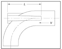
The cross tip velocity can be reduced to zero if an elbow installation is used. The thermowell must be installed against the flow, past the elbow joint. By reducing the cross tip velocity to zero, wake frequency ratio calcs are not necessary.
ASME PTC 19.3TW-2010 is not meant to be retroactive. The 2010 standard replaces the thermowell calculation portion of the 1974 standard; however, if there are thermowells currently in use with calculations performed per the 1974 standard, there is no need to perform new calculations. New calculations should only be performed when process conditions change. This includes changes in flow rates or process mediums.
To avoid many issues that can arise during the thermowell design process, users should thoroughly read ASME PTC 19.3TW-2010 or a whitepaper that explains the standard. Also, preliminary calculations showing passing results should be performed before the design is finalized. Once the thermowell order is placed, users should obtain official documentation showing calculation results.
Danjin Zulic is a Temperature Marketing Engineer at Emerson Process Management, Rosemount Measurement in Chanhassen, Minn. He has a Mechanical Engineering degree from Iowa State University and is currently pursuing his MBA at the University of Minnesota. Recently, he helped create “The Engineer’s Guide to Industrial Temperature Measurement,” a comprehensive handbook on temperature measurement in industrial processes. He also helped develop a free online thermowell calculation tool that is available at www.rosemount.com/thermowellcalc. Mr. Zulic can be reached at [email protected].
References
1. ASME PTC 19.3TW-2010, Section 6-7.
