Extreme processes require robust measurement tools
The standard approach to process measurement, as the name implies, works well for most operating conditions yielding accurate results while maintaining a safe working environment. However, when process conditions become extreme, standard approaches to measurement are insufficient.
The need for accurate and reliable measurement is critical to keeping people, the environment and facilities safe when applications are extreme with dangerous reactions and enormous amounts of heat and pressure. Managing process instruments to improve efficiencies and optimize performance under these potentially violent, flammable and toxic conditions can seem like a complicated riddle.
- Vibration
- Challenging flows
- Extreme process fluids
- Extreme temperatures
- Extreme pressures
For each situation, the major concerns as to what makes the condition extreme or difficult to deal with will be addressed, and solutions will be offered. When considering solutions to extreme conditions, the name of the game is specialization — specialized materials and software, custom design and signal processing, as well as considering viable alternatives. Together, these solutions offer both a practical and cost-effective solution to measurement under extreme conditions, keeping systems running smoothly and safely.
Vibration
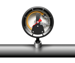
Vibration is a substantial problem when the vibration becomes large and extreme. Excess vibration can cause misalignments and failures in measurement equipment, especially delicate mechanical pressure gauges, with its springs and gears, eventually leading to device damage, leading to failures and leaks.
Fluid-induced vibration
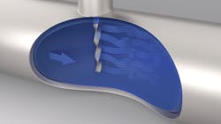
Depending on piping configuration, flowing fluids may induce varying degrees of vibration, causing wake shedding and peculiar eddy currents. These problems commonly occur at the site of a thermowell inserted into the fluid stream to measure temperature. The thermowell – inserted perpendicular to the fluid stream – causes vortices to form.
This is known as vortex-induced vibration (VIV), and while it can be tolerable in some situations, it can also lead to sensor failure and, in the worst case, fatigue failure in the thermowell itself, potentially resulting in containment loss because of bent or cracked thermowells. Using a non-intrusive thermowell with a new electric pressure gauge or traditional transmitter ensures reliable process conditions with extreme vibration.
Wire fatigue and breakage
If eliminating vibration is not possible, then accounting for potential damage to sensors and their wiring is crucial. One of the easiest ways to do that is by using redundant sensors, either in the same sheath or inserted separately. By comparing data from two or more sensors using programming on the transmitter, alerts can be triggered in the event readings differ or sensors fail. Even hooked up to the same transmitter, redundant independent sensors can reduce the probability of reading loss by 80%.
Thermowell durability
Where vortex-induced vibration is an issue, the conventional approach to strengthening a thermowell would be to thicken it and/or to make it very short so it can withstand the vibrations. Both approaches do have drawbacks though:
- A large diameter thermowell can cause significant time lag in responding to temperature changes and be difficult to mount while causing blockage in the pipe.
- A short thermowell may not extend far enough into the process fluid stream to deliver an accurate reading.
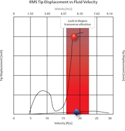
Irrespective of thermowell design, depending on the fluid velocity, the VIV may hit the natural frequency of the thermowell itself, causing increased vibration and significantly increasing metal fatigue. Some fluid velocities cause the VIV frequency to match the natural frequency of the thermowell, causing the amplitude to increase significantly.
While formulas exist to calculate required thermowell characteristics, outlined by the American Society of Mechanical Engineers (ASME) in its PTC 19.3 TW-2016 Standard, since the relationship between fluid velocity and VIV frequency is nonlinear, doing these calculations by hand can be difficult and time-consuming. There are free online tools, such as Emerson’s Rosemount Thermowell Design Software, which can handle the calculation after simply entering a list of 20 or so variables about the dimensions and operation characteristics. With that in mind, designers can easily size appropriate thermowells as well as see if existing units are suitable for new applications, offering greater flexibility in design without being bogged down in cumbersome calculations.
Avoiding fluid-induced vibration
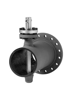
The best way to deal with a problem is to remove it at the source. Thermowell vibration from wake-shedding can be reduced by up to 90% by switching to a helical square design currently being used with great success in both wind stacks and deep-sea risers to solve similar problems. Emerson’s Rosemount Twisted Square thermowell not only suppresses over 90% of the destructive vortex effects but also allows for proper immersion that allows for a more reliable, safe and repeatable temperature measurement.
Challenging flows
A flow might be considered challenging or extreme when it exhibits one or more of the following properties: high-velocity, wide flow turndown range and large line sizes.
High velocity
Historically, piping guidelines limit fluid velocity to 7 ft./sec.; however, this practice is rarely considered anymore due to the higher cost associated with it.
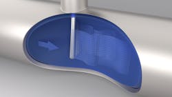
A simple method to solve both problems exist in the averaging pitot tube sensor, which takes the place of a more conventional single-orifice primary element.
The pitot tube is minimally intrusive to the pipe, works for bidirectional flow, self-averages velocity gradients for higher accuracy, and is suitable for use in liquids, gases and steam up to 300 ft./sec.
Widely variable flow range
Most process units are designed to operate within a narrow sweet spot, a known quantity that designers size equipment for. However, if flow varies greatly, it can be challenging to accurately size equipment. Coriolis flowmeters have an especially wide range but are not suitable for all applications, so conventional DP meters must be used instead.
When using DP meters, some users resort to the outdated practice of double stacking meters to expand the range. This is a cumbersome solution and one rendered obsolete by the existence of DP transmitters, which use electronics to expand the measurement range without losing accuracy.
Large line size
While flowmeters are highly scalable, increasing size can greatly increase cost. Once again, pitot tube sensors come to the rescue. They are well-suited to large line sizes and can be built for cross-sections up to 96 inches.
Temperature measurement for large lines run into the same issues of fluid-induced vibrating lines discussed in the previous section and is solved using the helical square thermowells.
Help with DP flowmeter selection
DP meters are a common technology for flow measurements because of their flexibility, but it can be difficult to choose the correct primary element. To make selection easier, using new online software tools simplifies the selection process. For example, Emerson’s DP Flow Sizing and Selection Tool guides users through the configuration process. Once an understanding of the process conditions is determined, such as piping size, process fluid and operating parameters, following the steps in these design tools will provide a full configuration description and part number based on vendor catalog.
Extreme fluids
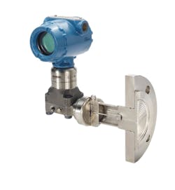
Diaphragm seals are manufactured from a variety of materials designed to minimize corrosion in each process condition, and they can be coated to withstand abrasion, so that fill fluids can maintain reliable temperature and pressure readings.
Avoiding wetted parts
While it is sometimes possible to use wetted parts that are protected by specialized alloys, it will depend on the application whether or not that might be practical. This is particularly true in the case of thermowells, which, due to their nature, would have a hard time surviving in extreme fluids. A common solution is to clamp temperature sensors to the outside of the pipe; however, these are vulnerable to external temperature fluctuation and heat dissipation through the pipe itself.
When external readings are the only option, specifically designed temperature sensors can still function accurately even when attached externally.
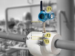
An algorithm built into the transmitter can correct for the heat dissipated by the pipe, and a pair of resistance temperature devices (RTD), one attached to the pipe and one at the transmitter, can compensate for environmental temperature fluctuations, ensuring accurate readings even in the harshest environments. This ability is found in Rosemount’s X-well technology, which provides an accurate process temperature measurement using just a surface measurement.
Designed for durability
Extreme fluids require equipment that can safely handle them. This can be as simple as coating with tougher alloys and specially formulated polymers, or even depositing a micro-thin layer of nanostructured carbon. Sometimes, simply hardening a surface is not sufficient. DP flowmeters are required to operate under many harsh conditions, and subsequently, the technology they employ has become more durable.
Thin diaphragms with unique flexing characteristics can provide the necessary degree of accuracy while protecting the more vulnerable meters.
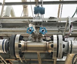
Flowmeters with fully welded spool sections, built-in isolation valves, temperature inputs and multi-orifice primary elements help minimize upstream and downstream pipe runs. Short impulse lines and close coupling of the DP transmitter minimizes plugging potential. Gate-type isolation valves and clean-out ports on the impulse lines allow rodding without shutting down the unit, and in the event of failure, the entire transmitter can be replaced without process shutdown.
These highly durable DP transmitters can also provide static line pressure readings and handle fluids up to 315ºC (600ºF), making them an ideal choice even under harsh conditions.
Extreme temperatures
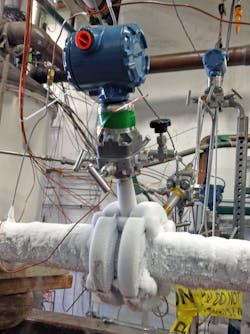
Extremes of both hot and cold can be equally detrimental to process equipment. While heat would generally be thought of as the worse of the two, cold, especially in the cryogenic range, can be just as destructive, if not more so.
Many of the techniques used to protect against extreme fluids are also effective against extreme temperatures, with some specialized variations.
Low environmental temperatures
While measurement devices themselves may continue to function in low environmental temperatures, the same cannot be said for the electronics that run them. Circuitry has a narrow operating range, and the cold temperatures in excess of -40ºC (-40ºF found in some Canadian and Russian oil pipelines) can cause them to stop functioning.
Under these extreme conditions, heat tracing and heated instrumentation cabinets can protect standard equipment, while specialized equipment, which is capable of withstanding such temperatures unaided, can also be deployed.
Measuring cryogenic temperatures
Even at cryogenic temperature ranges of -50ºC (-58ºF) and below, conventional RTD sensors are commonly used. RTDs come in a number of classes with different temperature ranges, anywhere from -50ºC to -200ºC (-58ºF to -328ºF). However, it is crucial that an appropriate class is selected. When even such low temperature ranges are insufficient, a thermocouple can be employed. Thermocouples are better suited for handling low temperatures than RTDs, as cold as -270ºC (-450ºF), and come in various types.
Most thermocouples lose linearity below -100ºC (-150ºF), but this is a known characteristic and easily accounted for with software built into the transmitter with no loss of accuracy.
DP flowmeters for low temperatures
While many choices exist, DP flowmeters with appropriate transmitters are well suited to cryogenic liquids such as liquid natural gas (LNG). In this case, it is particularly important to pay attention to sensor placement and material selection.
For conventional liquid applications, DP flowmeters are placed below the pipe to prevent trapping gases behind the diaphragm. In LNG applications, the reverse is true. By allowing gases to be trapped, an insulating layer is formed, protecting delicate equipment from the extreme cold.
Transmitter bodies made from stainless steel are easily able to withstand the cold, but other elementals such as gaskets and O-rings may not be able to, eventually causing them to become brittle and fail. For this reason, it is common to use fully welded impulse lines and move more delicate equipment away from the process fluid.
Isolating the transmitter
Dual fluids can allow the transmitter to be moved farther away from contact with the extreme fluid by having fill fluids specialized for both ambient and process fluid temperatures. When appropriately set up, these systems can be used in temperature ranges up to 410ºC (770ºF) or down to -105ºC (-157ºF).
Extreme pressure
As with all extremes, pressure — both high and low — presents its own unique challenges. Mechanical transmitters are able to operate for an extended duration within their designed range but can be damaged in the event of a pressure spike too far outside that range. Most general process instrumentation providers can support measurement up to 20,000 psi (1,379 bar), as most applications outside of this range are less common and more specialized.
Tough differential pressure flow measurements
Conventional DP flowmeters are designed to have a low pressure drop across the primary element, as little 30 psi (2 bar) at normal operating range, which can present a challenge when the process fluid has extremely high pressure, say 5,000 psi (345 bar). It can be difficult to measure a small pressure differential in an environment where the static pressure is hundreds of times greater than the differential.
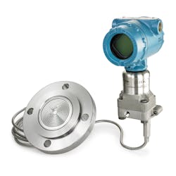
Some DP transmitters are designed for exactly this scenario, however. While they have a small measurement range, only up to 150 psi (10.3 bar), they can withstand static line pressure up to 15,000 psi (1,034 bar). They are highly resistant to overpressure and line pressure effects, allowing them to maintain high accuracy and stability, even under extreme conditions.
Working in a vacuum
Low pressure is anything less than atmospheric, and for the most part, standard equipment will continue to function under these conditions. The exception being that special attention must be paid to fill fluid. Under extreme lower pressure conditions, the boiling point lowers drastically, and evaporation is a big concern. Should this happen to the fill fluid, it can cause the whole system to fail and cause a shutdown.
Fill fluids must be designed to operate under these extreme low-pressure conditions as well as operating in sealed systems, using all welded construction to avoid allowing external air into the capillary system.
The right tools
As with all things, it is important to use the right tool for the right job. This is also true when dealing with extreme conditions. The technologies and practices described here are just the right tools, and none are a major capital project nor do they need to be executed on a grand scale. Solving the riddle is quite simple. Each improvement can be implemented individually for incremental gains, eliminating obstacles to effectiveness and profitability.
Connor Oberle is a global pressure product manager for Emerson’s Automation Solutions business in Shakopee, Minnesota, with responsibility for Rosemount pressure transmitters. He earned a B.S. in mechanical engineering from the University of North Dakota.
Timchan Bonkat is a global temperature product manager for Emerson’s Automation Solutions business in Shakopee, Minnesota, with responsibility for Rosemount sensors and thermowells. He earned a B.S. in electrical engineering from St. Cloud State University.
About the Author
Connor Oberle
Global pressure product manager for Emerson Automation Solutions
Connor Oberle is a global pressure product manager for Emerson’s Automation Solutions business in Shakopee, Minnesota, with responsibility for Rosemount pressure transmitters. He earned a B.S. in mechanical engineering from the University of North Dakota.
Timchan Bonkat
Global temperature product manager for Emerson Automation Solutions
Timchan Bonkat is a global temperature product manager for Emerson’s Automation Solutions business in Shakopee, Minnesota, with responsibility for Rosemount sensors and thermowells. He earned a B.S. in electrical engineering from St. Cloud State University.
