Why Are My Pumps Testing Below the Certified Pump Curve?
Pump Guy Mailbag: Certified Pump Curve Problems
Mr. Bachus,
I am a PE, at an engineering firm in New England. I have been working more than 20 years with the design of pumping systems for water authorities and municipalities. Recently I designed a booster pump station for a small town on the Atlantic coast.
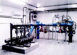
The station contains three centrifugal pumps in parallel, with suction and discharge headers on a skid. The pumps are end-suction, mounted horizontally. The water comes into an 8" suction header, with 3" suction pipes leading to each pump from the header.
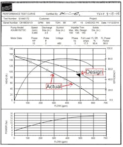
Each pump’s performance was certified at the pump factory at 88 ft at 500 GPM. Each pump has an impeller diameter of 150 mm, rotating on two-pole motors of 15 HP. We installed the skid at the municipal water plant and connected the pipes. We conducted the standard field performance test on each pump individually. All of the actual observed test points (25 percent, 50 percent, 75 percent, 100 percent, 125 percent design flow) fell below the certified pump curve, except for the shut-off head. The certified curve is below.
Certified water pump curve
Can you offer some insight to why these pumps tested below the certified test curves?
All the Best,
Bill A., P.E.
###
Hello Bill,
I will offer some thoughts, using your words. Your certified performance curves were developed at the pump manufacturer’s test facility. The pumps performed the way the factory pipe system allowed the pumps to perform.
Now the pumps perform differently on your client’s pipe system. The pumps perform the way your client’s pipe system allows the pumps to perform. The pipe system is the master. The pump is the slave.
You said all three pumps attain shut-off head when tested on site. Then each pump loses head when flow begins. This is an important point. It suggests the pumps are starved of energy on the suction side. Let me offer an example you can relate to.
Maybe you’ve had a clogged fuel filter on your car. The clogged filter screen starves the fuel injectors and the engine. The engine starts and runs properly at idle speed. But the engine will spit, sputter and shut down as you accelerate onto the highway. Your words and curves suggest your pumps are doing the same.
You describe these pumps as booster pumps. The population of the municipality is growing. The existing water delivery system is now inadequate. There is a desire to add 88 feet of energy at 500 GPM of additional capacity into the system.
I notice you are operating small pumps at high speed. The curve reveals each pump has the maximum diameter impeller on a two-pole motor (3,480 RPM). These pumps are maxed-out with no room to grow. Maybe the municipality has no plans to grow in the future.
Your certified curve doesn’t show the suction energy required (NPSHr) at different flows. Contact your pump manufacturer and get this information. You can bet the suction energy was adequate when the pumps underwent the certified test at the factory.
With the NPSHr and instrumentation to measure the energy deficiency, you will know how much energy you’ll need to add into the system to get these pumps back onto their performance curves. Can you believe it? Booster pumps for your booster pumps!
You said you have 3" pipe leading to the pumps from the 8" suction header. Not knowing your pipe metallurgy, I consulted a resistance chart for Schedule 40 Carbon Steel Pipe.
The liquid velocity through 3" Schedule 40 carbon steel pipe at 500 GPM is above 19.4 ft per second. (Verify the numbers with your specific metallurgy and schedule.) Standard piping practice calls for suction pipe velocity of 4’ to 6’ per second.
You might remember the Bernoulli Principle from the university. Bernoulli said "Pressure drops as velocity rises." The water’s velocity is at 0-to-low in the header. Then the water’s velocity is immediately jerked-up above 19’ per second through the 3" elbow and pipe leading to the pump. Turbulence and significant energy loss is the result.
This is more evidence suggesting your pumps are starved of energy. Install absolute pressure gauges (or transducers) on the suction nozzle of each pump, and on the suction header. Remember, NPSH values are absolute. A simple pressure gauge will only peg 0 PSIG and cannot report pressures less than atmospheric pressure.
Let the pressure differential tell you how much energy is lost between the header and the pump suction nozzle. The instrumentation removes the mystery!
Regards,
Larry Bachus, The Pump Guy
Larry Bachus, aka “The Pump Guy”
The Pump Guy is Larry Bachus, a pump consultant, lecturer, and inventor, based in Nashville, Tennessee. He’s a retired member of ASME, and lectures in both English and Spanish. You can contact him at [email protected].
The next Flow Control Pump Guy Seminar will be presented Jan. 12-14 in La Porte, Texas. For more details and to register, visit www.flowcontrolnetwork.com/pumpguy or contact Ashley Davidson at 205 995-1593 or [email protected].


