The common expression “Can’t see the forest for the trees” often applies to situations in motor and drive applications when problems occur and the process of diagnosing and correcting begins. Our fast-paced lives and desire to fix problems promptly, amid increased pressures from management and production, have forced us to prematurely conclude what is wrong with certain equipment failures or drive faults.
Depending on the size of the company and the levels of expertise among the engineering, technical and maintenance staff, problems are often misdiagnosed, further delaying the return of production in many instances. When a problem with a motor and drive appears, it is important to take the time to understand the overall situation and expected performance before attempting to direct a finger at the expected point of failure. While some companies may benefit from the resources of fully staffed engineering, technical, mechanical and production departments, others with multicraft expectations may rely on a limited number of maintenance personnel.
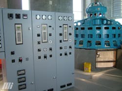
In either case, a normal tendency of a mechanic may be to conclude that the couplings, alignment, bearings and related hardware are not to blame, so it must fall upon the other departments. A multicraft maintenance person may have more training as an electrician and thus tend to push the failure out to someone with more technical experience, such as drive programming. Too often, our first reaction is to blame the most complicated piece of the puzzle, which means the AC, DC or servo drive. In all cases, it is important to note that the motors and drives are working together in, and as, a system — some are small and independent, and others are large and complex (as shown in Figure 1).
In the larger systems, many of them still can be broken down into smaller subsets, which are more manageable to the person doing the troubleshooting.
Tracking it down
First, it is always helpful if the person who is chosen to identify and correct the problem knows what the equipment does and how it is expected to operate. This may require talking to the operator first, who will always be able to share insight as to what happened right before the problem occurred or the tricks of getting the machine to operate efficiently. Many times, the operator will be required to take a back seat to their production supervisor, who may be able to relay the need for a quick repair but may also lack the day-to-day knowledge of how the machine runs.
When a drive is set up to communicate with a PLC or another drive, it forms its own network. However, this local network may be limited to these parts only and may not even have access to the plant’s main network, much less the internet. Mentioning the word “network” to anyone in the IT department can automatically produce a cautionary response. They may not realize that this network of drives and motors does not present a security threat to their plant, but may create resistance or even roadblocks to implement or expand the full potential of an automation system. As compared to the mechanics and electricians, everyone will strive to protect and defend their own department within their realm of knowledge and expertise.
Thus, to create a successful network of drives, motors and various controllers will typically require the involvement of someone from each of the plant’s departments. Even if their assistance is not necessary, it may be easier to receive their blessing in the beginning, as opposed to their displeasure when you begin to have problems with a network.
A deeper dive into the drive system
A typical automation system will include multiple drives and motors, but may also involve additional items in the field that are required to provide vital information. These will be used as I/O, or inputs and outputs, to the drives and controllers. A system may need simple devices such as relays, push-buttons, sensors, dancers, encoders, transducers or more complex parts like laser measurements and vision systems. When a drive system relies on these inputs to make a decision on how to control a motor, it brings up the “garbage in, garbage out” theory of operation.
It is important to realize that a drive operating correctly — and running effectively and efficiently — does not often start giving problems on its own. The parameters in the drive should always be stored or recorded as a hard copy to help return it back to its original state if someone decides to modify them to alleviate a perceived programming issue.
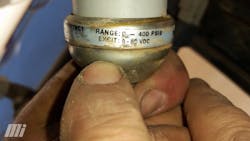
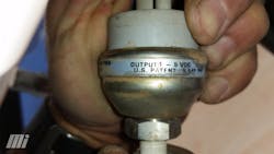
Take an airflow system that requires a pressure transducer and an ambient temperature probe as a guide for operating within the parameters of a desired recipe or target. Each of these will have a range of operation, for example, 0 to 400 psi and 0˚F to 120˚F, with the minimum at zero volts or zero milliamps, and the maximum at 10 VDC or 20 milliamps. If either of these are replaced with one that has a different range, say 0 to 500 psi or 0˚F to 100˚F, the drive system will still work, but not as efficiently as designed. (See Figures 3 and 4.)
It is possible for a sensor to fail open or closed as well, providing either minimum or maximum analog input to the drive. If the drive is not programmed or capable for these types of “loss of signal,” it will base its calculations on 0 psi, 0˚F, 400 psi, or 120˚F, rendering a host of operational problems that are not easily diagnosed. You may ask how a sensor with the incorrect range can find its way into operation, but it is easy if a mechanic or technician needs to get the machine running, and these are the only devices that they can find in the storeroom. After that, given enough time and some tweaking on the drive, the next person to work on this system will see that the pressure and temperature sensors are providing feedback, never realizing that it is incorrect and is the source of possible production issues.
Considerations
When approaching a drive system that has problems, it is important to look at it in a tiered fashion. What does this system require to operate? Are those basic components outside the drive giving the correct information?
If the drive’s input fails, maybe it needs an input reactor or fast-acting fuses, instead of the time-delay options that just happen to fit the fuse block. It is a good idea to power down the system and do spot checks on as many devices as possible. If you do not have a megger (megohmmeter), use a multimeter to check the resistance between each of the phases on the motor, and between each leg to earth ground, making sure that the leads have been disconnected from the drive. It is usually not critical, at first, to determine what the factory-specified ohm value should be, but to check for consistency between each of the readings. Any ohm value that varies from the others may lead to a motor “going” bad, which is enough to give the drive a trip like an earth fault or short circuit.
It is possible for a motor to run fine across the line, but still cause problems when operated from a drive. This is due to the sensitivity in the drive itself, which is looking for possible electrical disturbances that will eventually lead to a total motor failure.
Think through all angles
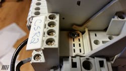
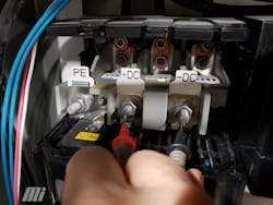
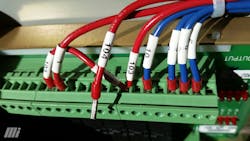
Do not rule out the simple things before beginning the work. A loose wire or a blown fuse have often been the root cause of a long downtime. (See Figure 6.)
Do not be afraid to ask questions, even if it means stepping outside your comfort zone. In addition, remember that it is never a bad idea to walk away from the machine or the surrounding swarm of people waiting on your immediate corrective action in order to think clearly and to consider different scenarios in your head. It is always better to pause slightly before moving ahead, as opposed to jumping right in the middle of a bad situation and making it worse.
Matt Asbill has been an automation specialist at Motion Industries for 26 years. For six years prior, he worked on government, aerospace and military projects. Asbill holds a Bachelor of Science in electronic technology from Missouri State University in Springfield, Missouri, and a Master of Science in engineering technology from Pittsburg State University in Pittsburg, Kansas. He is also a member of Phi Kappa Phi. For more information, visit MotionIndustries.com or download Mi’s free Motors & Drives e-book at https://tinyurl.com/yd54v98q.
Matt Asbill
Matt Asbill has been an automation specialist at Motion Industries for 26 years. For six years prior, he worked on government, aerospace and military projects. Asbill holds a Bachelor of Science in electronic technology from Missouri State University in Springfield, Missouri, and a Master of Science in engineering technology from Pittsburg State University in Pittsburg, Kansas. He is also a member of Phi Kappa Phi.
