The right pharma plant accessories
As Benjamin Franklin reminds us, little problems left unaddressed can have serious long-range consequences. Nowhere is this truer than in a pharmaceuticals plant. Small maintenance concerns can quickly lead to expensive problems. Fortunately for pharmaceutical manufacturers, a growing variety of options is available to address these concerns. This article offers a brief overview of some of the latest trends in accessories optimized for use in liquid pharmaceutical processing.
Wiper options
Consider a viewing port clouded by condensation that does not allow operators to clearly observe the process going on inside a vessel or to confirm that cleaning or sterilization procedures were conducted correctly. Without the ability to make regular visual checks and correct problems early, managers could later be forced to discard a contaminated or misprocessed batch, leading to product loss that could cost millions.
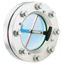
Image 1. Type I sight glass wiper fitted into a sight glass assembly
Other seemingly minor maintenance issues can also have unintended consequences. For example, a viewing port wiper can complicate the facility’s clean-in-place (CIP) or sterilize-in-place (SIP) procedures. If the wiper remains in contact with the port’s glass, the spray wand or spray ball might not be able to deliver the SIP/CIP solution to that spot, introducing the potential for contamination.
One of the most widely used port wiper options is the combination of a sight glass disc with a central bore hole and a Teflon wiper blade that maintenance personnel can rotate manually to squeegee condensation or other nonviscous liquids off the highly polished inside surface (see Image 1). These wipers operate vacuum-tight — and pressure-tight up to 90 psi — depending on the size of the sight glass disc. This approach offers the most economical way to add a wiper to an existing sight window. Wipers of this type are also customizable to allow maintenance personnel to push the handle down and lock the wiper shaft in place so the wiper blade is no longer in contact with the glass, allowing more thorough cleaning.
Another manual wiper option gaining in popularity is particularly appropriate for use in new construction of pressure and vacuum vessels that require test certification in explosion hazardous and nonhazardous operating areas. In Type II wipers, rather than being mounted through a hole in the middle of the glass disc, the wiper assembly is designed to go through the weld pad and retainer. The wiper is operated with a flexible shaft that engages at one end in the wiper blade holder and at the other in a lever-operated ratchet drive mechanism (see Figure 2). Because no bore exists through the glass, this wiper design is suitable for vessels that must be vacuum-tight and pressure-tight to much higher levels.
For environments that require remote monitoring of processes, wipers can be used in conjunction with an Ex-class motor drive and Ex-type camera to allow process engineers to observe what is going on in the vessel from a central control room. This option enhances worker safety by eliminating the need to climb to the top of a vessel.
Spray options
For applications in which a simple wiper blade is insufficient to clear liquids or particles from the port, a variety of spray units have been developed (see Figure 1), often for use in conjunction with a wiper assembly or a luminaire to increase visibility. These units are designed for intermittent, continuous or automatically controlled pressure cleaning of the glass’ inside surface. The spray nozzle connects to a supply line that delivers air, deionized water or another liquid that is compatible with the product during processing.
Spray rings (see Figure 4) are designed to deliver high-pressure, 360-degree cleaning to remove solids and liquids that obscure the view. Inserted between the connection flange and the sight glass assembly, a spray ring distributes rinsing fluid through a series of spray holes along the inside circumference of the ring. The spray holes are angled independently to clean the entire glass surface. The spray ring accepts liquids compatible with the product, or in the case of powder removal, high-pressure gases can be used such as air, nitrogen, carbon dioxide, etc. Spray rings are easily adaptable to automatic timed interval cleaning as well as manual valve-operated cleaning.
Shields up
In pharmaceutical applications, it is important to consider the effect of various process chemicals on the sight glass over time. Although borosilicate glass is significantly more resistant to chemicals than soda lime glass, glass is not chemically inert and will react even with water. Chemical resistance charts that illustrate the weight loss of glass when it comes in contact with various chemicals are available online. Glass can suffer chemical degradation from caustic or acidic substances and pitting from mild abrasion. These conditions may weaken glass to the point at which normal operating conditions may lead to a catastrophic failure. They can also obscure its transparency and possibly create crevices where bacteria can hide or leach into the process media. However, it is possible to extend the useful life of a sight glass with shields mounted on the process side of the glass. Made of mica, FEP or Kel-F material, these shields are not as transparent as glass, so some level of visibility tradeoff is required.
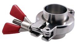
Image 2. Anti-galling clamp design
Put a clamp on it
Reliable, long-lasting clamps are critical to holding together the complex network of vessels, piping, tubing, valves, pumps, compressors, etc., in a batch process facility. They are essential to maintaining the required joint safety, cleanliness and efficiency in high-pressure and high-temperature manufacturing processes. To prevent leaks, these clamps must provide a consistent level of engagement around the circumference of the connection. Until recently, many of the clamps used in these settings were susceptible to galling, which occurs when a clamp’s bolt and nut become bound or locked together. A galled clamp can be extremely difficult to open to service the connection. In some cases, galled clamps have forced maintenance personnel to cut the clamps off vessels and piping to remove them.
Various factors can contribute to clamp galling, including the use of clamps made of the same grade of stainless steel for the bolt and nut. When over-torqued, they can become "cold-welded" together. Over-torqued clamps also exert excess pressure on the connection, which can lead to gasket intrusions into the connection, interfering with the flow of process material and allowing particles to collect. Overtorqueing a clamp can cause pieces of the gasket to shear off and be carried away, contaminating the product.
The cleaning procedures used in pharmaceutical plants can also play a role in clamp galling. Cleaning a clamp in a parts washer prior to installation can leave behind trace amounts of the sodium hydroxide used in cleaning solutions. Solution left behind in the grooves of the clamp will dry. This dried residue can contribute to galling by further binding the parts together.
The newest clamp designs optimized for pharmaceutical use (see Image 2) are made of 316-grade stainless steel, which offers higher performance than the 304-grade stainless steel used in most "commodity" clamps. The bolt, however, is made of a much harder Nitronic 60 stainless steel alloy. The clamp’s wing nut or hex nut is made of the 316-grade stainless steel. This change allows the clamp to withstand over-torqueing; If the nut is damaged, it can be replaced easily and inexpensively. In earlier designs, the nut would have been formed of the harder material and would have stripped the clamp bolt if over-torqued, which would have required scrapping the entire clamp.
Michael Curnutte is the director of sales for L.J. Star Inc. He joined L.J. Star in 2009. He may be reached at [email protected].


