5 temperature measurement mistakes with RTDs
The platinum resistance thermometer is a type of resistance temperature detector (RTD) that is commonly used to monitor and control temperature of industrial processes. They are very accurate when used properly; however, there are several factors that must be considered to achieve an accurate temperature measurement. Five common misconceptions or mistakes when using RTDs are:
- Assuming RTD interchangeability is the same as accuracy of measurement.
- Overlooking multiple contributors that add to the total measurement error.
- Not including installation errors in your accuracy calculations.
- Not enlisting your RTD manufacturer for assistance.
- Not knowing which standard your RTD meets.
RTD interchangeability versus accuracy
A common error when specifying RTDs is to mistake the interchangeability specification for the accuracy of the RTD. Interchangeability and accuracy are related, but they are not the same. Interchangeability is the tolerance band associated with the resistance value of the RTD. RTDs are manufactured to have a resistance reading of 100, 500 or 1000 ohms at 0°C, with 100 ohms being the most commonly used in industrial processes. IEC 60751 and ASTM E1137 are the two most common RTD standards in use today. These standards designate the tolerance or interchangeability as classes or grades: AA, A, B and C, with A and B being the most popular. Class A tolerance is ± 0.06% and Class B is ± 0.12% of the resistance at 0°C. These percentage values equate to ± 0.15°C for an IEC Class A and ± 0.30°C for IEC Class B when measured at 0°C.
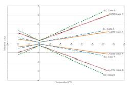
As the measured temperature moves away from 0°C, the tolerance band increases. Figure 1 shows this graphically.
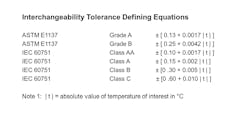
Interchangeability can be calculated for any temperature by using the equations shown in Figure 2.
Choose the equation that matches your RTD and enter the temperature (t) in degrees Celsius (for negative temperatures, drop the negative sign). Note that the ASTM tolerances are slightly tighter than the IEC values, so you will need to know to which standard your RTD was manufactured.
Estimating measurement error
Now that we know what interchangeability is, how do we calculate accuracy? If all you need is a rough estimate of the sensor accuracy, then adding about 15% to the interchangeability value will give you a good approximation. The additional 15% allows for other minor sensor error sources and average “in service” drift over time. This allowance is valid for the RTD sensor only and does not include any other installation errors, which are inherent in most processes. These other significant measurement errors associated with the installation itself need to be accounted for to determine what is commonly referred to as accuracy.
First, we should look at a couple definitions. Metrologists use the term “uncertainty of measurement” to express the magnitude of measurement error. One definition of measurement uncertainty is “the quantification of the doubt about a measurement result.” A measurement uncertainty calculation is a quantitative process that looks at the identifiable error sources and then combines them mathematically to determine a number that expresses the uncertainty of the measurement as a statistically significant value. The term accuracy is a qualitative term defined as “closeness of a measured value to a standard or known value.”
Let’s look at an example of an uncertainty calculation for a temperature measurement where we are maintaining a fluid temperature at 65°C running through a 4-inch pipe. Two groups of errors to consider are sensor errors and installation errors. Of these, the installation errors are usually the largest and unfortunately the most difficult to estimate.
Sensor errors to consider are the interchangeability, repeatability and stability. There are a few other minor errors such as insulation resistance, thermal EMF, hysteresis, self-heating and time constant that usually do not have much influence on the end result, so we will ignore those for this example. Typically, the most significant installation errors are stem conduction, vibration, controller and lead wire error. A common method of combining the errors is the root-sum-square (RSS) method. Each error is squared and added together, and then the square root is calculated. For our example process, the error sources are:
- Interchangeability of a class B sensor: ± [0 .30 + 0.005 | t | ] = ± 0.625°C
- Repeatability: ± 0.03°C
- Stability: ± 0.03°C
- Stem conduction estimated from RTD manufacturer’s specifications: ± 0.40°C
- Vibration: ± 0.05°C
- Controller: ± 0.10°C
- Lead wire: ± 0.08°C
The combined standard uncertainty using root-sum-square:
Installation error estimates and assistance from the RTD manufacturer
Installation error estimates can be difficult to make, and there are several sources to consider. The most common and impactful errors are stem conduction, RFI/EMI, vibration, mechanical shock, temperature cycling, thermal radiation and process fluid properties. A good source for assistance with error estimates is the RTD manufacturer’s data sheet or other product documentation. A complete data sheet that has performance specifications indicates that the manufacturer has tested their product thoroughly and understands the error sources that affect an accurate measurement. Sensors that have complete and comprehensive documentation sometimes have a higher initial cost but represent excellent value in providing a more accurate and repeatable measurement.
RTD standards
The most commonly used RTDs are defined by two standards: the IEC 60751:2008 and the ASTM E1137/E1137M - 08(2020). Each specifies the requirements and temperature/resistance relationship for industrial platinum resistance temperature sensors along with a few other performance requirements. Neither is very stringent in the requirements, and you will see several manufacturers exceeding the stated minimum requirements ostensibly for improvements in performance and long-term stability. As mentioned earlier, the ASTM and IEC standards have slightly different interchangeability tolerances, and this needs to be recognized when selecting the equation for calculating interchangeability. Consult the manufacturer specifications to see which standard their parts meet, or when in doubt, you can take the conservative approach and use the IEC standard equations. Another difference albeit minor is that the IEC describes the tolerance bands as classes, while the ASTM refers to them as grades, and this can provide a clue as to which standard the RTD meets.
Both standards define the temperature coefficient of resistance of the platinum resistance thermometer to be 0.00385 ohms/ohm/°C. This is the average change in resistance per temperature degree between 0°C and 100°C. It is important that the signal conditioning device connected to the RTD is set or programmed for this value. If not, a significant error will result, and it grows larger as the temperature moves away from 0°C. While platinum RTDs with a 0.00385 temperature coefficient are most common in today’s industrial applications, you may come across other sensing element materials such as copper or nickel and other coefficients including 0.003925, 0.003916 and 0.003902. In these situations, it is best to ask your RTD manufacturer to help with specifications and troubleshooting.
Summary
As you can see, there are several pitfalls to avoid for obtaining an accurate temperature measurement. Specifying the class or grade of RTD as defined by the standards is a good place to start and may be close enough for some applications, even after adding in the installation errors. For other, more critical applications, a closer look at the error sources and using a method such as RSS to combine them will ensure you have a measurement accuracy that will help provide efficient use of energy and produce consistent high-quality product in your process.
Bill Bergquist is a principal applications engineer and RTDologist at Burns Engineering with 37 years' experience in temperature measurement with RTDs and thermocouples in the aerospace, industrial and laboratory markets. For more information, email [email protected] or visit the Burns Engineering RTDology page on YouTube to view numerous how-to videos on temperature measurement.
Bill Bergquist
Bill Bergquist is a principal applications engineer and RTDologist at Burns Engineering with 37 years' experience in temperature measurement with RTDs and thermocouples in the aerospace, industrial and laboratory markets. For more information, email [email protected] or visit the Burns Engineering RTDology page on YouTube to view numerous how-to videos on temperature measurement.
