Pressure measurement, Part 3: Differential pressure level measurement
The first two articles in this series on pressure measurement focused on an overview of pressure measurement and the features, specifications and design considerations of pressure measurement equipment. This third installment will focus on using pressure measurement equipment to determine another process variable: level. More specifically, measuring the level of a liquid in a vessel.
Level measurement is one of the oldest and most common forms of measurement used in everyday life. An often-cited example of early level measurement is the Egyptians using level measurements of the Nile River 5,000 years ago to help predict drought, flood and the success of crops. Fast forward to today, and there are a plethora of technologies and level measurement methods. But all forms of level measurement fall into either direct or indirect methods.
Direct vs. indirect level measurement
As the name implies, the direct method measures the level variable directly and is independent of any other process parameters. For example, using a dipstick to measure the oil level in a car's engine is a direct measurement. An indirect level measurement method measures a variable other than level and then uses that variable to calculate a level measurement. Differential pressure level measurement is an indirect method, using pressure as the measured variable.
Differential pressure level measurement
Calculating the level of liquid in a vessel is relatively straightforward if the specific gravity of the liquid and the differential pressure at the spot to be measured are known. The relationship between the measured pressure and the height of the liquid being measured is expressed by:
DP = H*SG
where
DP = Differential pressure measured
H = Height of the liquid being measured
SG = Specific Gravity of the liquid
If the specific gravity of the liquid is known and the differential pressure can be measured, then simple algebra can solve for the height of the liquid (H).
H = DP/SG
It is important to note that this equation measures the height of the column of liquid where the pressure is measured, not necessarily the total height of the liquid. The point of reference is where the pressure transmitter is installed, and the overall height depends on the tank's geometry.
Transmitter connection methods
When using a pressure transmitter to measure the liquid level in a tank, there are a variety of connection methods. The three most common connection methods are direct mounting, impulse piping and remote seal capillary systems. Which connection method should be used depends on several factors: Where the transmitter will be mounted onto the tank, whether the tank is vented to the atmosphere or pressurized, and, if pressurized, whether a gas sealing (dry leg) or liquid sealing (wet leg) method is used.
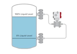
Most differential pressure transmitters will indicate which process connecting port is for the high and low sides. These indications refer to the relative high- and low-pressure sides, not the physical location where the measurement is taken. The highest pressure in a tank is at the lowest measured location since the column of liquid is the tallest there. Generally speaking, the high-pressure side of the transmitter is connected to the lowest physical point of measurement on the tank, and the low-pressure side of the transmitter is connected to the highest physical point of measurement on the tank.
Direct mounting
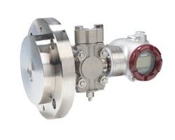
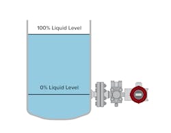
Some processes allow the transmitter to be mounted to the tank without impulse lines or remote seals. These instruments are often described as direct-mount transmitters and come in many designs. A standard gauge pressure transmitter can be screwed onto a threaded process connection that is welded to the tank. Flange-mount transmitters are also attached directly to tanks. These flange-mount models typically also include a special attachment mechanism to improve accuracy and protect against corrosion. Direct mount differential pressure transmitters are commonly used on open tanks as one side of the transmitter will be vented to the atmosphere as the reference pressure.
Industrial pressure transmitters can be heavy. Mounting brackets should be used to support the transmitter, when necessary, since orientation, gravity, vibration, thermal cycling and other variables can have deleterious effects on the integrity of the installation.
Impulse piping
Impulse piping is a small-bore piping that is used to connect a point in a pipe or tank at which a process parameter is to be measured by an instrument. Its purpose is to convey the precise process conditions to the transmitter.
For differential pressure level measurement, two primary types of impulse piping are used: dry and wet reference legs. Proper care must be taken to select the correct type based on the application.
Dry reference leg
A dry reference leg, as the name implies, is a reference leg to the differential pressure transmitter that should remain dry and free of the process fluid. A dry reference leg can be used if vapors given off by a process fluid will not condense into liquid droplets under normal operating pressures and temperatures. This vapor fills the reference leg that is connected to the low-pressure side of the differential pressure transmitter.
Wet reference leg
If vapors given off by a process fluid could condense into a liquid at expected ambient pressures and temperatures, then a dry leg reference cannot be used. In this case, a wet leg reference must be used. A wet leg reference contains the process liquid or another non-reactive liquid. The design and construction of a wet reference leg can be complicated. Always consult an expert to ensure proper procedures are followed.
Remote seal capillary systems
Impulse-line connections from instruments to tanks are relatively straightforward and cost-effective, but they have limitations. As mentioned above, condensation can occur, compromising measurement accuracy. Additionally, they may leak due to weak seams or joints in the piping, get plugged with solids from the process or even freeze if exposed to cold.
Sensitive and expensive components, especially the diaphragm, can be damaged if they are in direct contact with corrosive or abrasive media. If the electronics are located too close to high heat, they can be damaged. These issues can be avoided by using remote seals connected to the instrument via oil-filled capillary tubes. Instead of physically connecting the pressure transmitter directly to the process, it is separated by the seal and capillary. As the process media pushes against and deflects this special remote seal diaphragm, the pressure is transferred through the oil-filled capillary to the instrument.
The remote seals are connected to the transmitter via capillaries. Capillaries are durable yet flexible tubes of varying diameters designed to withstand cracks or leaks. They are typically filled with silicone oil that resists thermal expansion or contraction, though other oils are available for extreme process conditions. The transmitter, capillary and seal can be connected via threads but are often carefully welded together to eliminate leak paths for a reliable and repeatable measurement.
Remote seal systems are highly engineered solutions to the problems mentioned above. The diaphragm material can also be customized to ensure chemical compatibility with the process media. Instead of a standard stainless-steel diaphragm, Hastelloy C, titanium or other exotic wetted materials can be used to protect against corrosion.
Open tank (unpressurized) measurement
There are two primary types of tanks regarding differential pressure level measurement: open (unpressurized) and closed (pressurized). Open, non-pressurized tanks are vented to the atmosphere; there is a clear path from the tank to the surrounding environment, and the air pressure acting on the liquid equalizes with the atmospheric pressure.
Thus, the reference pressure is equal to the atmospheric pressure. The pressure measured at the point of transmitter installation is due to the weight of the liquid only as opposed to a closed pressurized tank, where the pressure measured at the point of transmitter installation is equal to the pressure of the liquid plus the pressure of the gas.
Open-tank piping
For open tank piping, the low-pressure side of the transmitter is open to the atmosphere, and the high-pressure side of the transmitter should be connected to the tank where the lowest liquid level to be measured is located. The transmitter can be connected in several different ways. Direct mount, impulse lines or remote seals are all typical piping setups for open tanks. So, if the conditions allow, this setup could be as simple as a single differential pressure transmitter mounted directly to the tank.
Closed tank (pressurized) measurement
Closed, pressurized tanks are not vented to the atmosphere, so the reference measurement is more involved. A gas phase often exists on top of the liquid. This gas pressure could be above or below atmospheric pressure. So, this gas pressure must be compensated for to produce an accurate level measurement. A change in the gas pressure will cause a change in the level transmitter output and introduce an error without this compensation. Moreover, the gas pressure may be so high that the pressure caused by the column of liquid becomes insignificant.
For these reasons, a pressurized closed tank application requires an accurate reference connection. The reference connection is located at the top of the tank and feeds into the transmitter's low-pressure side. Its purpose is to compensate for the gas pressure above the liquid so that an accurate level measurement can be made without error. If there were no reference connection, the transmitter would measure the liquid level plus the gas pressure.
The following equation illustrates how using the reference condition cancels out the effect of the gas pressure allowing for just the hydrostatic head of the liquid to be measured.
Differential Pressure = P(high) - P(low) = H*SG
Closed-tank piping
Closed tank piping configurations tend to be more complicated as the reference pressure is not the atmosphere. In an impulse piping configuration, the low-side reference leg is either filled with a column of liquid (wet leg) or a suitable dry gas (dry leg). As previously mentioned, wet leg and dry leg are terms used to describe whether or not vapor in a tank will condense into a liquid form and must be considered when designing a system. While relatively simple in concept, impulse piping installations can be challenging to maintain. Impulse lines can leak and plug and require insulation or heat tracing.
Ambient temperature effects
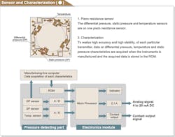
Ambient temperature can significantly affect the accuracy of pressure transmitters in any of the above-referenced applications and configurations. However, some differential pressure transmitter manufacturers offer a solution to compensate for these ambient temperature effects: sensor characterization. During the manufacturing process, the sensor is subjected to a range of temperatures and pressures. Data on how these temperatures and pressures affect the sensor are acquired during this process. This data is then stored in the transmitter's memory and referenced as a correction factor during use, allowing the transmitter to remain stable and accurate.
Conclusion
Deriving the level of a liquid from pressure measurements is a simple but clever way to use physics to generate additional information about the world around us. Hopefully, this article was helpful in understanding how pressure can be used to measure level. The next and final article in this series will take pressure measurement one step further using physics, math and engineering to measure flow rate with differential pressure.
Ryan Bennett is a product marketing manager for Azbil North America, based in Denver, Colorado. He holds a B.S. in Industrial Distribution from the University of Alabama at Birmingham. Ryan has worked in various roles at Azbil North America, with a current focus on product management and marketing. He can be reached at [email protected].
Azbil North America
About the Author

Ryan Bennett
Product marketing manager
Ryan Bennett is a product marketing manager for VorTek Instruments in Longmont, Colorado. He holds a B.S. in industrial distribution from the University of Alabama at Birmingham. Bennett has had a strong focus on steam metering, control and distribution throughout his career. He has worked in various roles at VorTek Instruments, with a current focus on new product development and marketing. Bennett can be reached at [email protected].


